Using GTEM Cells for Immunity Testing
Upgrading an in-house emissions system to include RF immunity testing can provide significant benefits for product development.
Many small- to medium-sized businesses that in vested in in-house EMC RF test facilities are equipped only for RF emissions testing as opposed to having a full setup that includes RF immunity testing. Often this restriction is due to a past business decision based on financial prudence, but the decision also was likely based on the reduction of business risk.
The business risk lies with possible punitive action by the government if other parties complain that your equipment interferes with the operation of their equipment. Confirming emissions compliance with an emissions test setup reduces this risk significantly.
Sooner or later, there will be a change in the criteria on which the business decision was made. Sometimes the decision is revisited due to a new customer�s insistence on proof of RF immunity compliance or possibly a complaint of product susceptibility from an existing customer.
Whatever the reason, when forced to conduct RF immunity testing, a company soon realizes that developing a product by repeated submission, correction, and resubmission to an independent test lab is expensive. The benefit of in-house immunity capability then becomes abundantly clear.
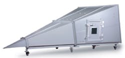
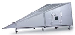
The main topic of this article is the upgrade of an in-house RF emissions system to include RF immunity testing. The system uses a gigahertz transverse electromagnetic (GTEM) cell (Figure 1), but the basic approach is applicable to the upgrade of systems using other types of TEM cells. For simplicity, the upgrade will meet the immunity test frequency range of 80 MHz to 1,000 MHz per EN 61000�4�3.
A key feature of GTEM cells is the capability to operate up to many gigahertz. As a result, they are well suited for conversion to the higher frequency requirements of pending and future immunity standards.
Emissions Testing vs. Immunity Testing
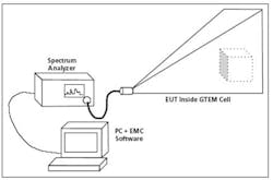
With RF emissions testing, the equipment under test (EUT) is placed into the cell and switched on, and the emissions are monitored. A preliminary scan is run to identify emissions hot spots, and then the hot spots are closed in upon and checked against emissions limits.
This is repeated for other EUT orientations within the cell. The key purpose of the system software is to set the spectrum analyzer start and stop frequencies and produce graphics for report generation. Figure 2 shows a typical emissions test setup.
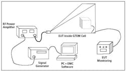
TEM cells are reciprocal. That is, a field in the cell generates a voltage at the RF connector, and conversely, a voltage injected at the RF connector creates a field within the cell. With immunity testing, predetermined spot-frequency voltages are injected into the RF connector to create test fields.
Figure 3 shows a typical RF immunity test setup. Software steps the signal generator through a frequency/output-power data table created during system calibration. The power amplifier boosts the spot frequency signals to achieve the necessary field strength. The EUT is exposed to each field for a fixed dwell time, and its performance is monitored for susceptibility. The entire procedure is repeated for other EUT orientations within the cell.
The EUT must continue to perform within specification during the immunity test. When the EUT has a visual display, this can be monitored to check that the display does not change, assuming that the TEM cell has a viewing window.
The visual approach has several weaknesses including the assumptions that the display can be seen whatever the orientation of the EUT and that the display changes if any parameter goes out of specification. Owing to these weaknesses, it is preferable to monitor vital points in the EUT via the filtered connections supplied with most TEM cells.
System Considerations
The equivalence between a GTEM cell and an open area test site (OATS) has been formally endorsed, so a claim of emissions compliance is entirely feasible. Equivalence between a GTEM cell and an anechoic chamber has not been endorsed, so a claim of product immunity compliance using a GTEM cell is less straightforward.
The safest route is to use the immunity system for precompliance testing only. This does not remove the cost of independent testing but curtails it by drastically reducing the number of fix and repeat cycles. Should the decision be made to pursue full compliance, the test results can be used as evidence in the compilation of a technical construction file (TCF) for each product.
This is not too onerous if enough evidence is accumulated that points to close equivalence to test lab results. The uncertainties in RF immunity testing are notoriously high, so proof of exact equivalence is unnecessary. The TCF would hold all results of previous crosschecking with accredited test lab results.
Examples of prototype products failing immunity under the same conditions in both the cell and at an accredited test lab are ideal, and the case is strengthened if the in-house system has ample over-testing capacity. For precompliance, a 30-W, 80- to 1,000-MHz amplifier will do. For full compliance, an amplifier on the order of 100 W is necessary to ensure adequate power overhead.
An important system consideration is whether to use open-loop field generation or incorporate closed-loop field generation. Open-loop generation simply applies the field at the same level as when the cell was empty. Closed-loop generation monitors the field strength during the testing of the EUT and changes the power output from the signal generator to maintain the field at the prescribed strength.
The closed-loop approach has several flaws. Only one point in the field is monitored, and the presumption is made that all other points at the face of the EUT change in a like manner. That is, if the field-probe output indicates a 20% drop in field strength, then it is assumed the field strength at all places at the EUT front face dropped by 20%. It is not possible to measure the field at the face of the EUT for the simple reason that the face is in the way, so this is a brave presumption to make.
To see the issue here, look at the wave dynamics taking place in the cell. If the EUT has a reflecting surface at the face in question, such as a metal or screened panel, then the wave will be reflected. This will be recognized as the principal on which RADAR is based.
Metal is a conductor, so at the EUT face, the net electric field is zero. To be zero, the forward and reflected fields must be equal but opposite in phase. So within the cell, there is an incident wave and a reflected wave.
Constructive and destructive interference occurs, resulting in a standing wave with peaks and nulls. Where the peaks and nulls occur depends on the phase of the incident wave.
Phase is not controlled in the closed-loop system so undertesting by reacting to a peak or overtesting by reacting to a null is a matter of chance. Clearly, this affects the capability to repeat the test results, an important inclusion for TCF files.
A wide variation in field strength is allowed between measurement points in the field calibration plane. To keep the field strength the same after the EUT is inserted, which field strength should the loop lock to�the lowest, highest, average, or the field strength stipulated by EN 61000-4-3?
It makes things clearer if we remind ourselves of the basic point of this immunity exercise: to prove, as best we can, that nearby electronic emitters giving out a certain level of noise will not cause the EUT to malfunction. In real life, a nearby emitter does not change its output to compensate for a null or peak. It simply continues to emit the same field level.
Counter to this particular point is the change in the field inside the cell due to EUT loading. This argument has great merit but flies in the face of the proven equivalence of GTEM cells to OATS.
If it is widely accepted that no remedy is required for EUT loading during emissions testing, where is the rationale in applying one for immunity testing? GTEM cells and OATS are both reciprocal, with the OATS suited to immunity testing except that it is illegal to emit high RF fields into open space.
Whatever the case, there already is a great deal of uncertainty built into radiated immunity measurements, much of it caused by the attempts to contain and control high RF fields. Closed-loop field generation serves only to compound this uncertainty.
Additional Test Equipment Required for Conversion
Key components including a PC, a spectrum analyzer, and RF cables/connectors already exist from the emissions test setup. Table 1 lists the requirements of both test systems.
To convert to immunity capability, we need to add a signal generator, a power amplifier, and a field meter. The existing software also may need to be upgraded. Remember that the preamplifier is of no use since the signal generator can drive the power amplifier to its maximum output power.
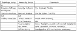
Some way of monitoring the vital signs of the EUT also is required. Interconnecting cables and connectors should be checked for sufficient power rating. `
Signal Generator
The system does not need a particularly high specification unit. A signal generator that covers 80 MHz to 1 GHz with built-in amplitude modulation (AM) and remote-control capability will do. Since suppliers aim at satisfying several markets, many signal generators exceed these requirements.
RF Power Amplifier
The bandwidth should be a minimum of 80 MHz to 1,000 MHz. Most suppliers of amplifiers covering this band offer a lower start frequency. For precompliance field generation, the amplifier needs to be on the order of 30 W. This rating has built-in overhead for the extra power required for modulation with AM waveform shape preservation.
For full compliance, the power should be on the order of 100 W. Broadband RF power amplifiers are expensive, so it makes sense to protect the investment from accidental damage caused by excess reflected power. Some matters to be taken into consideration when exploring available amplifiers are the following:
� Watch out for amplifiers that have optional remote-control and power-monitoring capabilities. There is no pressing need for remote control since the amplifier is used as a fixed gain block that only needs to be on during testing. But unfortunately, many suppliers only provide reflected power protection if you buy the remote-control option.
� Amplifiers with forward and reflected power indication have a directional coupler built in, so an external coupler and power meter are not needed.
� Beware of marketing hype surrounding the subject of reflected power. Statements such as �continues to operate into high voltage standing wave ratio (VSWR)� shouldn�t be taken at face value. All too often, the amplifier does not shut down, so the performance takes a hit as protective mechanisms kick in and reflected power changes the amplifier gain.
Sometimes the statement should read �some of our amplifiers continue to operate� since the claim of high VSWR immunity often only applies to lower power models. If convinced of the advantage claimed, make sure that it applies to the amplifier under consideration.
Keep in mind that massive amounts of reflected power indicate that something is very wrong in the RF test setup; that is, a connector is loose or open. Regardless of the cause, this has to be investigated and resolved. Protection against accidental abuse is the key requirement here.
� Astute amplifier houses offer AM waveform linearization on broadband amplifiers. The main benefit here is the reduction of power overhead.
� Housing all the system test equipment in one rack makes for an orderly arrangement. Let common sense prevail over neatness by positioning the amplifier close to the RF input connector to minimize cable losses. RF power is expensive to generate; don�t throw it away as cable heat.
Field Meter
The field meter is used mainly for field-strength measurements during system calibration and system checking prior to a test run. The market offers few choices for broadband isotropic probes, and the higher the frequency capability, the higher the price.
Given the questionable case for using the field meter as part of a closed-loop system, money may be saved by investigating whether remote control permitting connection to the PC is absolutely necessary. The meter should come with test data allowing calibration factors to be integrated into the system calibration table.
Immunity Software
Controlling software is a must since manually changing the frequency and power settings on the signal generator for each spot frequency would be extremely time-consuming. If possible, the same software used for emissions testing should be used for immunity testing. It takes a long time to become accustomed to a software package, and it would be a shame to lose the familiarity gained.
As an example, the suppliers of TILE software provide upgrades at no cost as part of continuing customer support. Beware the offer of free software as part of a deal on other equipment. It simply could be a ruse to lock out other equipment suppliers.
EUT Monitoring
EUT monitoring can be as simple as a brassboard with LEDs and test points or as elaborate as an analog-to-digital board that can be configured for any EUT. It makes sense to work with the software supplier when exploring suitable analog-to-digital boards, especially regarding interfacing with the PC.
System Commissioning
The main activities for system commissioning are the following:
� Initial system checking at low field strengths to ensure all component parts are functioning correctly.
� Generation of the calibration table (no AM applied) per EN 61000-4-3. The amplifier gain is not constant with frequency so the signal generator power is changed to compensate. Also, the field-strength meter response is not flat with frequency so factor in the error data provided by the manufacturer.
� Generation of the calibration table with 2-dB (30-W amplifier) or 4-dB (compliance) field strength overhead.
� With AM applied, confirmation of waveform purity for all points on all calibration tables. The spectrum analyzer can be used to check for distortion in the modulation index in the frequency domain. Alternatively, an oscilloscope with a detector diode can be used to check for distortion in the time domain. The power required to create the AM waveform is 3.2 times greater than the peak power required to create the unmodulated signal.
� Repetition of tests to prove repeatability.
� Creation and implementation of an action plan to collect and compare cell data with test lab data.
� Provision of formal staff training in conducting immunity tests.
Future Higher-Frequency Capability
The high-frequency capability of the GTEM cell allows immunity testing beyond 1,000 MHz. With upcoming standards requiring testing to many gigahertz, this is a useful feature. The system design can be adapted to switch in higher-frequency equipment at appropriate places during the test. Most software controls the switches already built in, but care should be taken regarding the physical location of the switches.
At higher frequencies, cable loss is significant. External switching via a single hub requires long interconnecting cables with the result that up to half the available system RF power may be lost as heat. Full consideration should be given to multiband power amplifiers with internal band switching since the internal connections are comparatively short. Switching losses are less of an issue when switching low power signals since the signal generator usually has ample power overhead.
About the Author
Thomas Mullineaux, the chief writer at HighTechWriter, is an RF engineer with 15 years experience in leading design teams. HighTechWriter, 3332 Florista St., Los Alamitos, CA 90720, 562-400-4501, e-mail: [email protected]
February 2005
About the Author
Comment About the Article
To join the conversation, and become an exclusive member of Electronic Design, create an account today!

Leaders relevant to this article: