Any switching system can connect A to B. Only a well-designed one delivers top performance.
Well-designed test systems have a minimum of three major subsystems: computing, instrumentation, and switching. Functional test systems add device under test (DUT) power and DUT output loads. Of these, the switching subsystem is arguably the heart because all of the other subsystems need to interact with it. It�s important, then, to get it right.
A switching system may need to switch signals from DC to more than 25 GHz, millivolts to thousands of volts, and milliamps to amps. System capacitance from wires and relays can cause timing and crosstalk problems, and inductance can cause ground loops and voltage spikes. The number of points to be connected to instrumentation and to the DUT can range from a few to several thousand.
Switching speeds which vary over two orders of magnitude depending on the type of switch can greatly affect overall system throughput. With such a wide range of performance expected of the switching subsystem, it is not surprising that there are many types of switches to choose from.
All modern commercial off-the-shelf (COTS) switching solutions are implemented as card cages, including VXI, PXI, and several lower cost vendor-specific solutions. In all of these, switches are offered in many different configurations and with a choice of five major types: field-effect transistors (FETs), reed relays, armature relays, RF relays, and microwave relays. The characteristics of each of these are shown in Table 1.
Switch Types
FETs are great if you need very high-speed switching and can tolerate higher on-resistance. They have virtually infinite lifetimes, but being solid-state devices, they are more prone to static damage than mechanical relays and generally can�t tolerate as high a voltage or current as relays.
Latching armature relays generally are used to measure very low voltages where low thermal offsets are important. Armature relays (latching and nonlatching) also are the best choice for high voltages (>100 V) or currents (>500 mA).
Reed relays offer higher switching speeds than armature relays and have higher voltage and current handling capability than FETs. Reed relays inherently have higher thermal offsets than latching armature relays. For the latching armature relay, a short impulse activates a coil that in turn moves a lever which is not connected electrically or magnetically to the contacts.
In a reed relay, however, the contacts are ferrous to complete the magnetic circuit consisting of the coil and the contacts. The contacts form a thermocouple with the copper PCB traces, which generates a voltage on the leads that varies with temperature. This effect can be minimized, but doing so tends to make the relay more expensive.
RF and microwave relays are constructed similarly to armatures. They generally are intended for applications in which low insertion loss, voltage standing wave ratio (VSWR), and specified characteristic impedance, typically 50 or 75 ?, are the most important factors.
General-Purpose Relays
General-purpose (GP) relays come in all five types. The most commonly used relays are single-pole single-throw normally open (SPST-NO, Form A) and single-pole double-throw (SPDT, Form C). Form B relays normally are closed versions of SPST relays and commonly are not used because hazardous voltages can be present if the relay loses power.
The most flexible choice for low-frequency applications is the armature type because it can handle higher voltages and currents. GP relays typically are used to connect power and loads (resistors, solenoids, and lights) to DUT pins. They also can serve as switch closures to ground or to a power supply for DUT inputs.
Multiplexers
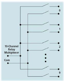
Multiplexers can be implemented using all five relay types and are designated as n x m. For example, a 1�4 has one common terminal and four switched positions. Microwave relays basically are single-channel coaxial multiplexers with common grounds. Figure 1 shows the schematic diagram of a typical relay multiplexer. Note that there are two relays per channel.
Inductive coupling in the measurement path can cause the generation of ground loops in the low lead. To break these loops, it is necessary to switch the low as well as the high leads. This is particularly useful for capacitance and inductance measurements at frequencies below 1 MHz.
With two-wire multiplexers, floating signals can be applied and measured. However, it is important that the DMM have good common-mode rejection when making floating-type measurements.
Matrices
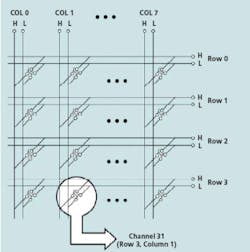
Figure 2 shows an example of a typical relay matrix where any row can be connected to any column. With a matrix, any source or measurement instrument can be connected to any pin of the DUT. Two-wire matrices are used for the same reasons as two-wire multiplexers�to break ground loops, reduce thermal offsets, and allow floating measurements.
Armature and reed matrices often are constructed using relays having a single coil controlling both the high and low switches. This minimizes any heating differential across the switch pair, providing lower thermal offsets. Matrices are sometimes constructed using separate relays for the high and low sides to allow the relay banks to be operated single-ended. Use of independent relays offers only a first-order correction for thermal offsets.
The flexibility of a matrix comes with a price: For the same measurement task, it can take more relays than using a multiplexer, resulting in increased initial cost. For example, suppose you need to apply one high/low signal to 70 different pins on a DUT at different times. Using COTS relay cards, it would require either a single 70-channel two-wire multiplexer costing about $1,500, or five two-wire 4�16 matrix cards with the four rows connected together on each card costing about $5,000. However, that extra $3,500 means you can feed four signals (not just one) to 80 points (not 70), and the same signal could be applied to more than one point at the same time if needed.
It is not common to need all sources and all measurements at the same time in a functional test system. If the DUT has built-in self-test, the testing can be partitioned into manageable chunks requiring only one or two stimulus instruments and only one measurement device to be active at the same time.
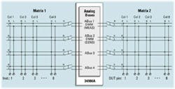
This greatly minimizes the number of relays needed which lowers the cost of the test system while allowing it to handle modules with large pin counts. Figure 3 shows this concept in detail. Some switch/measure units, such as Agilent�s 34980A, have a built-in internal analog bus. As shown in Figure 3, one relay matrix allows connection of eight floating instruments to the four-line two-wire bus plus the internal DMM. Additional matrices can be attached to the external bus and extended to handle as many DUT pins as needed.
Data Acquisition
Data acquisition systems may have thousands of measurement points spread out over a large area. Typically, identical measurements such as resistances or DC voltages are performed by scanning a single DMM through all the points. A relay multiplexer is best used for these applications.
If ultimate reading speed is desired, the parallel measurement of multiple points using several DMMs also can be used, but it becomes cost-prohibitive in terms of both instrument cost and physical space once the number of simultaneous measurements gets above about eight.
Here�s an example of a data acquisition application: An aircraft wing may have 1,000 measurement points using thermocouples and strain gages and transducers to measure temperature, deflection, air pressure, and airflow.
Armature relays, which take about 15 ms to switch, might be used because of their extremely low thermal offsets and wired to the test system via shielded twisted pair wire. A typical armature relay multiplexer card might have 70 channels, so 15 cards would be needed to scan 1,000 points.
In a high-noise environment, a longer DMM integration time is often needed to acquire quiet readings, perhaps one AC line cycle or as much as 20 ms plus reading overhead. One thousand readings at 40 ms each (15 ms for the relay and 25 ms for the reading) will take 40 s. If this time is too long, multiple DMMs or faster relays are possible options.
Fortunately, there are switch/measure units with built-in DMMs that can do this. With two of these units, each having a DMM and filled with eight 70-channel armature relay multiplexers, 1,120 two-wire channels can be measured at 6.5-digit resolution with low noise in about 20 s for about $25,000.
Functional TestA functional test system must apply power and signal stimuli to a DUT and then measure its responses. For many applications, the signals are <100 VDC at <500 mA and the outputs may require inductive loads capable of high peak voltages up to 500 V and currents of 30 A or greater. The source impedance of a solid-state relay usually can�t be tolerated, so it is normal to use reed or armature relays to connect the sources to the DUT since their on-resistance is very low.
For low-frequency applications in manufacturing, FETs or reed relays are the best choice because of their switching speed. In the lab, where test execution speed is not as important, any type of relay that is suitable for the voltage, current, and frequency of interest can be used.
Functional test applications require a lot of dynamic reconfiguration: Different sources may need to be applied to the same DUT pin at different times, and a variety of measuring instruments may be used to measure the responses. In addition, test systems often are used for different DUTs at different times, requiring all the stimulus and response signals to be mapped to completely different pins. The best way to address this is by using relay matrices.
Here�s an example of a typical automotive switching application: An engine control module might have 200 pins requiring power and ground, DC stimulus to simulate oxygen and throttle sensors, AC stimulus to simulate knock sensors and cam/crank/top-dead-center inputs, and various switch inputs to ground or battery voltage. In addition, serial communications such as CAN, four to eight fuel injector outputs, an ignition output, and a number of other solenoid and light bulb outputs are needed.
One solution is to feed up to 16 instruments onto four two-wire analog buses using one reed relay matrix and to feed up to 192 DUT pins onto that four-line bus via six more 4�32 two-wire reed matrices. DUT power, ground, and load connections are made via high-current GP relays. Through judicious use of high-speed relays, fast DMMs, and DUT-assisted test in which serial commands break module functionality into manageable pieces, it is possible to test such a module in a production environment in as little as 9 s.
Summary
Choosing the right relay and associated switching architecture is not trivial. You need to think about capacitance, inductance, resistance, current, voltage, grounding, guarding, cost, and expandability. There are a number of good choices available in COTS switching systems: FETs and reed, armature, and RF/microwave relays come in a variety of configurations to help you get the job done right.
About the Author
Brian Wood has been with Hewlett-Packard and Agilent Technologies for 30 years. He has designed hardware, firmware, and software for in-circuit board test systems and driver software for automotive and functional test systems. He has been a technical marketing engineer for the past 10 years. Mr. Wood graduated with a B.S.E.E. from the University of Arizona. Agilent Technologies, 395 Page Mill Rd., Palo Alto, CA 94303, 800-829-4444, e-mail: [email protected]
February 2005


