Testing a product to destruction keeps it from breaking later in the field.
Failure is not an option for Brooks Automation controllers. A single field failure can cause thousands of dollars in lost productivity for their customers and warranty repair losses for Brooks Automation.
The Chelmsford, MA-based company produces controllers for an array of vacuum and atmospheric robots used in manufacturing semiconductor wafers. To make the most durable controllers for their customers around the globe, Brooks engineers needed to find out how their controls would withstand the test of time.
Short of a time machine, the best way to predict the future of a product is highly accelerated life testing (HALT). Working closely with Sypris Test & Measurement, a nationwide testing and evaluation services provider for the aerospace, military, medical, and commercial electronics industries, Brooks has performed extensive HALT tests on its robotic controllers. Beginning eight years ago with the Brooks Series 7 Controllers, HALT has played a major role in subsequent designs and paid off in more reliable products, higher customer satisfaction, and fewer warranty returns.
HALT
HALT simulates product aging by subjecting equipment to a series of adverse conditions. The object is to find breaking points or weaknesses. Applying stresses well beyond product operating and design limits compresses time by replicating the types of experiences a piece of equipment has over a lifetime. The process typically lasts three to five days depending on how quickly a particular unit stabilizes between steps, the length of time to verify operational functionality of the unit under test, and the downtime for evaluation and repairs.
HALT comprises five environments:
-
Cold step stress (CSS) testing that subjects a product to increasingly colder temperatures, typically in 10�C steps.
-
Hot step stress (HSS) testing that subjects a product to increasingly warmer temperatures, typically in 10�C steps.
-
Temperature cycling testing (TCT), which cycles the product between its hot and cold limits; the typical thermal rates of change are 40�C/min to 60�C/min.
-
Vibration step stress (VSS) testing, which subjects products to 6 degrees of freedom (DoF) vibration over a wide, modally rich frequency spectrum. The vibration typically is stepped up in 120% increments starting from 3 to 5 acceleration root mean square (grms) to 60 grms.
-
Combined environment testing (CET), which subjects the product to combinations of VSS and TCT.
Throughout the process, test engineers are looking for two types of failures: hard or total failures and soft or temporary failures. The purpose is not to see if a component is going to work at -40�C, for example, because most components aren�t built to withstand such extremes.
Rather, HALT helps designers determine the equipment�s tolerance margin beyond the designated operating range. A component breakdown within 5�C or 10�C of its operating range suggests weaknesses over a product lifetime and the potential for latent failures.
HALT is most effective when there is a close partnership between experienced test-lab engineers and knowledgeable product designers. Product designers should have an intimate understanding of component functions and weaknesses and how the product is expected to perform. Test engineers need thorough knowledge of how to properly apply environmental and mechanical stresses to precipitate failures using HALT protocols.
Series 7 HALT
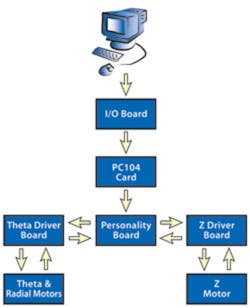
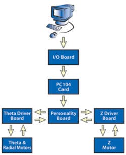
The Brooks-Sypris HALT test partnership began with the Series 7 Robotic Controllers. Figure 1 illustrates the organization of the various boards in the controller. Commands from the PC are optically isolated by the I/O Board and passed directly to the Personality Board or via the PC104 Card for translation to machine code. The Personality Board controls radial, rotational, and Z-axis robot motion. Communication with the driver boards is bidirectional to accommodate feedback from encoders on the relevant motors. HALT can unmask failures at all these points.
Figure 1. Robotic Controller Block Diagram
All the tests were performed at the Sypris laboratory in Burlington, MA, using a QRS410T HALT Chamber produced by Screening Systems. The 2.5-ft wide and tall enclosure is capable of temperature transitions of 60�C/min with a range of -100�C to 200�C. The controller inside the chamber stayed connected to a robot on the outside.
CSS Test
At -30�C, the controller experienced a hard failure in the lithium battery on the PC104 Card, the controller�s computerized core. This failure wasn�t much of an issue because -30�C was already well below the controller�s operating range.
The team installed a heater inside the unit to keep the battery above -20�C so the chamber temperature could drop lower for further tests. Typically, HALT will continue to the edge of the test chamber�s limits or a point where the conditions are hard-failing the whole unit, whichever comes first.
At -40�C, the robot reset itself during a rotational move. The failure appeared to be caused by a loss of power through the DC/DC converter. The team tried to warm the converter, but the unit didn�t respond. The engineers then replaced the theta driver board, but the failure recurred at -48�C. As a result, the team decided a more durable DC/DC converter was needed.
HSS Test
At the high temperature limits in HALT, hard failures tend to occur in poorly designed components and parts that already run hot, such as power supplies.
At 70�C, the Motion Controller Computer (MCC), the part of the personality board on the controller where all the servo motion calculations occur, ceased operating. For the robot arms to move, an operator issues a command, which then is executed by the MCC. It sets a trajectory path to the motion and sends the proper current signals to the motors to set the proper speeds.
Test engineers determined that the oscillator for the MCC was causing the soft failure, which was fixed when the temperature was reduced to 60�C. The team recommended finding a better oscillator.
TCT
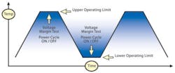
In the TCT, engineers quickly cycle the chamber temperature up and down over the product�s operating range determined during CSS and HSS. The engineers vector the chamber air across the test product to facilitate thermal transition and stabilization. During rapid thermal cycles as well as at low temperatures, soldered joints and interconnects typically show weaknesses, and circuitry timing troubles manifest themselves.
The cycling, performed as rapidly as the chamber allows, is an exploratory test that helps establish and verify the operating temperature range. Thermocouples measure temperature at various spots on a component, and the data is logged.
Figure 2 diagrams a typical TCT over the low and high operational limits of the test unit. The dwell time at each extreme is long enough to allow the largest mass of the unit to reach the required temperature and be subjected to verification and margin testing.
Engineers found no notable new failures during the TCT on the Series 7.
VSS Test
The input table vibration consisted of modally rich broadband energy from 5 Hz to 5 kHz, a spectrum that most effectively precipitates a wide range of failures in a test product.
The vibration table energy was measured through a suitable filter and equalized and controlled by applying digital analysis and control techniques to produce equally spaced lines across the specified test-frequency spectrum. Each line had a maximum bandwidth of 10 Hz. The recorded power spectral density data was displayed as an X-Y graph of G2/Hz vs. frequency, and the overall energy was calculated in grms.
The VSS tests caused no critical failures on the controller.
CET
The final HALT step repeated TCT simultaneously with the VSS. The engineers put the controller through two thermal cycles for each vibration grms level. No actionable failures were found.
Based on the results of the first round of HALT, the engineers changed several parts and implemented design changes in the controller. The two companies put the fresh design through another full set of HALT and found no new failures.
Series 8 HALT
Lessons learned from the Series 7 tests and field data were incorporated into the Series 8 Robotic Controller designs. Again, the controller inside the chamber stayed connected to a robot on the outside.
CSS Test
The programmable logic device (PLD) failed at -20�C. The PLD was an off-the-shelf device, so the engineers decided to find a more robust PLD to incorporate into the design.
HSS Test
The controller ceased communicating with the robot and the aligner at 90�C, a harsh environment well beyond the operating range. Communications returned at 80�C, and the engineers determined that no action was needed because the component functioned well within design specifications.
VSS Test
A capacitor canister leg broke at 10.4 grms. The team specified a stronger capacitor housing. Also, a PEM nut that holds the circuit board to the controller chassis broke. The engineers specified a better PEM nut and spaced the circuit board farther from the chassis.
HASS Testing
HALT is a vital part of the design phase, but to get a better idea of how a product will fare in practical use, further testing is important in the manufacturing phase.
After determining the actual limits of temperature and vibration during HALT, Sypris engineers extrapolated those numbers to HASS levels that allow a unit to be quickly and aggressively screened for defects.
With the actual operating margins determined by HALT, HASS allows higher stress levels than conventional environmental stress screens (ESS). The more aggressive levels of HASS maintain a high level of robustness that can�t be achieved by classical ESS methodologies. HASS can drastically shorten the test time required to screen a product, resulting in fast throughput and long-term cost savings.
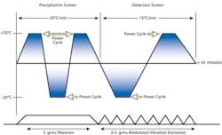
Figure 3 shows the HASS profile used on the controllers. The test consists of three thermal cycles over the unit�s operating range of -20�C to 70�C. The first two cycles, with a thermal transition rate of 30�C/min at a continuous vibration input of 5 grms, represent the precipitation screen�stresses meant to expose manufacturing problems, poor workmanship, and other issues. In the third cycle, the detection screen, stresses are reduced to the point where the test unit should operate fully. This allows engineers to verify 100% functionality of the controller.
Figure 3. Actual HASS Profile Used for Brooks
Proof of Screen
Prior to subjecting a product to HASS, a proof of screen (POS) is required. The POS helps determine if the HASS levels are high enough to uncover weaknesses but not so high as to remove too much life from the test unit.
A POS usually consists of applying the proposed HASS levels 20 times. The POS usually is done on units pulled right off the line that have gone through the normal manufacturing process with all the implemented changes from HALT, with the latest design revisions of all parts and boards.
For the Series 8, a POS was performed using 20 iterations of the HASS profile on a nonshipping production unit. The POS successfully validated the HASS profile by determining that the profile did not result in excess stress on the unit.
For HASS, Brooks incorporated a regimen for 21 units randomly selected from the first 100 units during initial manufacturing of the series. HASS helped verify that the changes after HALT were successful.
But testing did reveal additional operating and manufacturing issues. To address the problems, Brooks implemented a technician�s protocol of checks to be performed prior to wrapping and shipping a unit. That checklist remains in use today as an integral quality-control measure.
Savings and a Longer Life Expectancy
As part of the product development road map at Brooks Automation, HALT is deployed today in the early stages of the product life cycle and is a key step before any product leaves the alpha phase.
Brooks continues to partner with Sypris to conduct HALT and HASS tests. The combined HALT/HASS testing has been a boon to product development at Brooks Automation, inspiring continuous improvement in the company�s robotic controllers. HALT tests on the Series 8 Controller alone have saved an estimated $3 million by preventing warranty returns and more than doubled the product�s life expectancy.
About the Authors
Toufic Najia is a manager of reliability test engineering at Brooks Automation. He has more than 18 years experience in the reliability and test fields, 10 years with Brooks performing HALT on all generations of robotic controllers. Mr. Najia was awarded a B.S.E.E. from Louisiana Tech University and is a member of the Institute of Environmental Science Technology. Brooks Automation, 15 Elizabeth Dr., Chelmsford, MA 01824, 978-262-2572, e-mail: toufic.najia@ brooks.com
John Baron is director of operations at Sypris Test & Measurement Test Laboratory. In 20 years with Sypris, he has performed HALT for the telecommunications, medical, semiconductor, military, and avionics industries. Mr. Baron is a graduate of Wentworth Institute in Boston with a B.S.E.T. and a member of the Institute of Electrical and Electronics Engineers, the Society of Automotive Engineers, and the Institute of Environmental Science Technology where he was awarded the 1999 John Martin Outstanding Young Member Award. Sypris Test & Measurement, 53 Second Ave., Burlington, MA 01803, 781-743-0240, e-mail: [email protected]
FOR MORE INFORMATION
on HALT/HASS testing services
www.rsleads.com/503ee-177
March 2005


