Feel the thrill as your LEGO Mindstorms robot autonomously navigates a harrowing course.
Two things strike fear in the heart of an engineer: One is performing a live demonstration, and the other is competing with the creative design abilities of 12-year-olds. Kids think outside the box much of the time and succeed in trying things that more experienced adults are certain won�t work. So it was with mixed emotions that I undertook an evaluation of the LEGO� Mindstorms�, a high-tech teaching aid.
The Robot Negotiating a Difficult Turn
Introduced by LEGO in 1998, the basic Mindstorms kit comprises more than 700 LEGO pieces, sensors, motors, gears, shafts, a programmable controller, and an infrared programming tower. There are three sensor input ports (1, 2, 3) and three output drive ports (A, B, C) on the controller. Only the types of parts and the quantity of ports limit what you can create.
The controller is called the RCX, and several programming environments exist for it. The educational version of Mindstorms comes with the graphical ROBOLAB� language, developed jointly by National Instruments (NI), Tufts University, and LEGO DACTA, the educational division of LEGO. The mission of Tufts� Center for Engineering Educational Outreach is to improve and facilitate engineering education in the nation�s schools, and ROBOLAB is part of that effort.
Getting Started
Everything you need except a PC is contained in one 9″ � 12″ � 15″ box: several plastic bags of LEGO parts, two plastic trays with compartments for the parts, the RCX and programming tower, a Mindstorms tractor construction guide, and the ROBOLAB CD. Installation was straightforward with the many program files and examples taking 165 MB on the PC�s hard disk.
Three large posters illustrate how to get started. After installing the software, insert six AA-size batteries that power the RCX. Finally, determine what version of the infrared programming tower you have, install a 9-V battery if necessary, and connect the tower to the appropriate PC port. In my case, the tower simply connected to the PC�s USB port and didn�t require a battery.
Additionally, I visited the LEGO website and downloaded the Quick Start Guide to Computer Control and Robotics Using LEGO MINDSTORMS for Schools. The 29-page booklet guides you step-by-step through setting up the hardware and software and explains each of the training exercises in detail.
Now you really are ready to go. The ROBOLAB application runs like any other and once initiated offers three choices: Administrator where setup is done, Programmer where examples are listed, and Investigator where you run your own programs. The training material is presented on two levels, a series of very basic Pilot exercises and a number of more advanced Inventor examples.
Working through the examples is fun and very fast thanks to the infrared programming feature. You simply turn on the RCX, position the infrared tower opposite the red window on the RCX, and select the RUN arrow. The completed percentage of the download is displayed on the screen, and a short series of ascending tones from the RCX indicates successful completion.
You have the option of downloading up to five separate programs to the RCX, selected by repeatedly pressing the Prgm button. You also can debug the hardware sensors and outputs without running a program. Pressing the View button causes the value of the ports to be displayed on the integral LCD along with a small arrow pointing to the relevant port. This feature makes it easy to set the light sensor threshold, for example.
Although I mostly was concerned about the programming aspect of the evaluation project, the Mindstorms-ROBOLAB kit actually is aimed at two important learning areas. In a paper delivered at the 1999 ASEE/IEEE Frontiers in Education Conference, the authors commented on their study involving students ranging in age from 10 to 18 years:
�Most students favor more laboratory work for physics or science classes, since laboratory work is helping them to understand the subjects better. They thought that the use of LEGO construction sets in education is helpful and interesting, and could be used in mathematics, physics, and computer classes. About half of them were still using LEGO construction sets at home. Some were familiar with several concepts of robotics, but less than 50% were able to solve a simple gear arithmetic exercise.”1
The kit supports learning about mechanics as well as software programming, both key elements of robotics. Before you can program a mechanical model, you have to design and build it. It helps to have had previous exposure to LEGO.
Although my son has been a software engineer for several years, as a child he built LEGO models. Well, not exactly models, but creations, and lots of them. My involvement with his projects ensured that even many years later the model-building part of the exercise was no problem.
Model Description
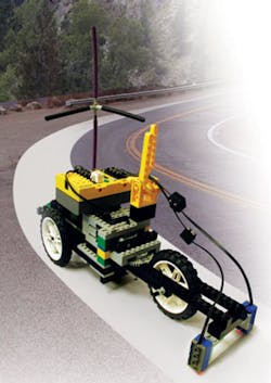
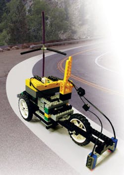
My project was a tricycle with gear-reduction rear-wheel drive via a motor connected to port B and front-wheel steering via a combined spur and worm-gear drive from a motor connected to port A. The goal was to follow a randomly shaped trail of 4�”-wide white paper without getting lost.
Two light sensors were equally spaced either side of the front wheel 3�” apart and 3�” ahead of the axle. The steering algorithm design attempted to keep both sensors over the white surface. In addition, a mock high-gain twin-element antenna made from flexible shaft material was mounted at the left rear and driven from an auxiliary power takeoff.
The Mechanics
Following a white line is basically a steering problem, but the speed with which the steering correction takes place must be scaled to match the forward motion of the vehicle. In fact, in response to a colleague�s suggestion, I reduced the main drive motor gear ratio to increase the forward speed and found, for example, that the steering algorithm couldn�t handle sharp corners, a condition easily dealt with when moving more slowly.
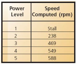
The drive motor gear ratio is 64:1, achieved in two cascaded 8:1 stages. The tires have a 3�” diameter or a circumference of 10.2″, and the measured speed at power level 3 is about 10″/8 s or 1.25″/s = 75″/min. The motor speed is 64 � 75/10.2 = 470 rpm.
The motor power level can be assigned one of five different values, but I found that low values tended to stall or run unevenly. Also, when both motors are running, the battery power is shared, so they do affect each other. The results of a simple test program that only drove motor B are shown in Table 1. The values are the average of three runs at each power setting.
The steering is controlled by motor A operating through a 24:1 worm-gear drive followed by a further 8:1 spur-gear reduction for an overall ratio of 192:1. A worm-gear drive also is used for the auxiliary power takeoff that rotates the radio antenna at the rear of the vehicle. A 1.5:1 spur-gear reduction is followed by an 8:1 worm-gear drive, causing the antenna to turn through roughly 270� every second.
The Steering Algorithm
Initially, following the white path seemed relatively straightforward: Simply drive the steering motor in the appropriate direction to return the errant sensor to the path. That approach only worked to a limited degree.
Because the steering did not return to a neutral position after a bearing correction had been made, a straight track was followed as a snake moves, in a series of curves. Also, if there was a sharp bend in the paper path, the steering soon hit a mechanical stop but kept on driving until the forces were sufficient to break apart the LEGO joints.
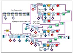
The algorithm used two light sensor forks (comparison/decision blocks) in series to determine the left/right sense of the needed correction and ensure that the motor could never be simultaneously commanded to drive in both directions. Only if one sensor output was below the set threshold would the other sensor output be considered. If both were above the threshold, they both were physically above the paper track, so no correction was required. Figure 1 shows an annotated version of the final program.
The light sensors output a level between 0 (no reflection) and 100 (complete reflection). As a default, the threshold is set to 50, but I found that the readings from the office carpet and the white track ranged from about 35 to 52. To improve the sensing reliability, I set the thresholds to 41, which worked well throughout the evaluation.
After experimenting with the vehicle and observing the major shortcomings, the algorithm was revised to measure the amount of correction applied so that subsequently it could be removed. In ROBOLAB terms, variables are represented by containers. So, the value of a blue or a red container was incremented when a correction in one or the other direction was made.
Two container forks were inserted along with container decrement instructions. Each fork controlled removal of the bearing correction after it had been made. This was accomplished by driving the steering motor in the opposite direction for the same number of loops and with each loop taking the same 0.2 s as those that caused the actual correction.
This level of software worked much better than the first attempt, but the vehicle still came apart at a sharp corner. It needed some limit switches.
I have a hardware engineering background, but I took a risk and opted for software steering limits. Because the motor drive already was done in discrete bursts, limiting how much correction could be applied was just a matter of recognizing when the maximum number of commands had been issued.
I inserted two more container forks and set their limits to 10, equivalent to a correction lasting about 2 s. This value works well with the steering mechanics. Even when attempting to follow a right angle in the track, the steering approaches full lock and stops until the white path has been reacquired by the sensors. For software limiting to work correctly, the model must start the course with the steering in a straight-ahead neutral position, and when a steering correction has been made, it must be totally removed.
To ensure that my office colleagues would know that the vehicle was coming, I included a task fork. One task takes care of steering, as described, while the other plays a short but melodious fanfare as the vehicle starts off. Also, to give some feedback on the state of the control system while operating, a light attached to port C is turned on when no corrections are being made.
A Last-Minute Corner Case
In the later stages of testing, I found that the vehicle only turned sharp corners to the right. There was no problem if only one sensor left the track. Either sensor was repositioned correctly. However, if the right sensor left the track at a sharp left turn before the left sensor, the steering simply straightened out and the vehicle lost its way. The intended action was for the steering to remain locked to the left until the white path was reacquired by the sensors.
The error occurred because of the order in which the sensor fork decisions were made: the left sensor took precedence. This meant that when the left sensor left the track first in a sharp right turn, the branch leading to the right sensor fork never was taken. Of course, that meant that none of the correction removal logic came into play, so the steering remained at full right-hand lock as desired for a right-hand turn.
If the turn is to the left, the right sensor leaves the track first and the steering reaches full left lock. Unfortunately, as soon as the left sensor leaves the track, its steering correction logic takes priority and drives to the right for 2 s. This action removes the full left-hand lock, and the vehicle carries on straight ahead. No pun intended, but indeed, this problem was found by considering all corner cases!
To remove the algorithm�s sensitivity to the turn direction, I added a blue container fork in the red path and vice versa. This change prevents normal steering correction if a correction in the opposite direction has already occurred but for some reason has not been removed�as in the case where the sensor has remained off the track in spite of applying a full-lock correction.
Making the change was not without challenges. I encountered an error message claiming that I had connected two tasks together. I hadn�t, but neither had I taken care to merge the various fork paths in the correct combinations. The two paths from a fork must be combined in the same merge symbol. In other words, nested If-Then-Else constructions have to be completed at each level.
Designing With ROBOLAB
I had worked a little before with NI�s LabVIEW, so the general idea of a graphical programming environment was familiar to me. Nevertheless, I appreciated a number of very clever innovations in ROBOLAB that cater to the nonprofessional or even the first-time programmer.
I particularly liked the use of colors to distinguish one container (variable) from another as well as to correlate the start and end of nested loops and jump commands. All the icons operate in a similar manner, attributes and conditions being supplied from a separate pallet.
Also, control of the multifunction cursor is very simple. The tab key causes the cursor function to cycle through its four capabilities: a select arrow, a PDF-type hand, a wiring tool, and a numeric insertion cursor. As in LabVIEW, wiring terminals on the icons blink and automatically connect themselves when brought close together. I found this method of control very easy to understand and use because I always knew what function to expect as I moved the cursor around my design.
But, designing a software routine is only part of the story. What makes the Mindstorms product really stand out is the ease of download afforded by the infrared link to the PC. It literally takes only a minute to make a simple change and download the new program version to the RCX. It�s so fast that even kids won�t become bored easily.
And, of course, that�s the whole idea. ROBOLAB is a great learning tool that�s as suitable for 12-year olds as college students. When I developed the steering algorithm, I concentrated on only the relevant icons. Actually, ROBOLAB functionality extends to image acquisition and processing, Internet and e-mail communications, multimedia sound, and beyond. The only important limitation of this teaching aid is the student�s imagination.
Reference
1. Lau, K.W., et al, �Creative Learning in School With LEGO Programmable Robotics Products,� 29th ASEE/IEEE Frontiers in Education Conference, November 1999, San Juan, Puerto Rico.
Acknowledgement
Thanks to National Instruments for providing the Mindstorms-ROBOLAB kit that made this evaluation possible.
April 2005


