VXS promises to solve the data transfer requirements of real-time embedded systems as faster processors and interfaces emerge.
The VMEbus, well into a third decade of widespread deployment, continues as the dominant bus structure for high-performance embedded systems. In an industry characterized by a steady succession of new device offerings with speed and density increases every few months, VMEbus has retained this leadership position not simply because it is based on a sound electrical and mechanical architecture. Indeed, the major reason for its longevity has been a series of performance and feature enhancements, the latest of which is VXS, a switched serial backplane fabric for VMEbus.
The Switched Fabric Connection
I/O standards are constantly evolving for performance. With bit data rates now in the gigahertz range, the new generation of switched serial fabrics can easily rival earlier parallel counterparts.
One of the major benefits of new serial interfaces is the reduced number of signal lines and smaller connectors and cable. This delivers enhanced system density, simpler system integration, lower installation costs, and easier maintenance.
Another benefit is the capability to use copper cables for low-cost local connections or optical cable for fast, long-haul data-transmission channels. The physical layer can be made completely transparent to the protocol layer.
Yet another benefit of serial links is the capability to gang together multiple serial links to boost data throughput. Since the signal within a single bit link contains embedded clock and timing information, each link can propagate on its own across the channel, and transceivers at each end can handle the multiplexing and demultiplexing for 1�, 4�, 8�, or 16� ganging in low-level hardware-layer devices.
Once the benefits of switched serial fabrics became apparent, embedded systems vendors sought ways to take advantage of this technology for a wide range of interconnection needs: boards-to-peripherals, boards-to-boards, chassis-to-chassis, and facility-to-facility. Switched serial fabrics are attractive alternatives to existing technology for front-panel interconnections and extremely appropriate for backplane data traffic to augment or replace the conventional parallel backplane bus.
Choosing a Fabric
Embedded system vendors now are faced with choosing from among many contending switched serial fabrics. Infiniband is aimed primarily at server and storage-system connectivity for box-to-box links. StarFabric�s strength lies in providing transparent serial links between PCI devices.
PCI Express is Intel�s initiative for connectivity between processors and boards in PCs and workstations. Hyper Transport is AMD�s solution for chip-to-chip and board-to-board connections in PCs. RapidIO targets chip-to-chip and board-to-board connections for real-time commercial off the shelf embedded systems and has strong support from Motorola.
These five fabrics are all vying for position. Aside from some valid technical pros and cons for each fabric, the key issues for switched fabrics tend to be business related.
For example, which major vendors are backing each standard? How easily can these new fabrics be integrated into existing software operating system environments? What components are available for bridging to existing hardware and processors? What kinds of switches are available? And finally, can the components achieve a sufficiently high volume of production to make them inexpensive, power efficient, and easily connected?
VXS for Real-Time Solutions
During the last few years, the VITA 41 Committee of the VMEbus Standards Organization has been defining VXS. It will assure the continuing popularity of VMEbus by allowing legacy boards to coexist with the new VXS versions as they become available. The specification defines a VXS payload card, a VXS switch card, and a connector scheme for various possible backplanes to support VXS.
Because of the fabric wars, the VXS specification was designed to be fabric agnostic: There are five subspecifications, one for each of the five fabrics. The basic switched fabric architecture chosen to connect the boards across the backplane was a ganged 4�, full-duplex serial channel. This means that each interconnect supports data flow in both directions simultaneously.
Serial bit rates are defined for frequencies up to a maximum of 10 Gb/s although lower frequencies are supported today. With the 4� ganging and a nominal bit frequency of 2.5 GHz, both the input path and the output path can move data at 1 GB/s.
VXS Payload Card
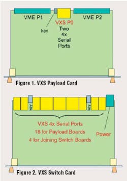
The VXS payload cards are processor, CPU, memory, and data-converter 6U VMEbus with the VXS interface added. They have standard P1 and P2 connectors that implement the standard VME64� backplane interface. A new P0 backplane connector mounted between P1 and P2 handles two 4�, full duplex-switched serial ports.
VXS Switch Card
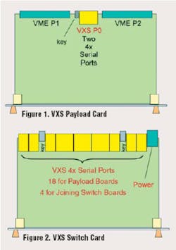
The VXS switch card has a 6U VME board form factor but, unlike the payload card, no P1 and P2 connectors (Figure 2). Instead, the space normally used for the P1 and P2 connectors along the rear edge of the board is populated with a power connector and connectors that handle up to 18 4� full-duplex serial links. The VXS switch card implements the crossbar switching to connect payload cards together.
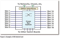
VXS switch cards can have any number of crossbar switches and serial ports. They also may include other interfaces to networks for communications and storage devices as well as front-panel serial ports to other VXS switch cards in the same chassis or adjacent racks.
Optical serial ports could be used for remote high-speed data transfers. Figure 3 shows one possible diagram for a VXS switch card supporting the maximum number (18) of serial interfaces.
VXS Backplane
The VXS backplane can take on many different layouts to accommodate specialized system needs but normally will handle two to 20 payload cards and one or more switch cards. The standard board-to-board pitch of 0.8 inch is maintained throughout, and other VMEbus card-cage mechanical hardware, such as card guides and frames, is compatible.
The objective is to connect the two 4� serial links of each payload card to links on the switch card(s) to support the necessary board-to-board connectivity. Some smaller systems could require only a few payload slots and a very simple switch card while others may need to use a full-width backplane and multiple switch cards to handle the required traffic.
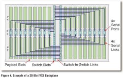
Figure 4 shows a 20-slot VXS backplane that holds 18 payload cards divided equally in each half and two switch cards occupying the two center positions. One serial link from each payload card connects to one of the switch cards while the second serial link of the payload card is wired to the other switch card.
Since each switch card has a maximum of 18 serial link connections, all 18 payload cards can be connected to each other through two redundant paths, specifically through both of the two switch cards. This dual redundancy is attractive for many applications requiring fault tolerance and high availability. As shown in Figure 3, the two switch cards also have additional serial links that join switch cards together, providing yet another path for routing.
Switchless VXS System
Although fully implemented VXS systems will use one or more VXS switch cards for routing data between payload cards, these switch cards are not available at this time. To enable engineers to start developing with VXS today, ELMA-Bustronic and Pentek have created a switchless VXS system. This five-slot system works without the need for a switch card.
The new switchless VXS system serves as a platform for developing, characterizing, and testing new VXS products and is cost-effective for smaller applications and demonstration systems. Compliant to the VITA 41� specification, the five-slot system combines three payload slots plus two conventional VME64� slots and allows design engineers to take advantage of the VXS technology immediately. Pentek�s Model 6821, a 12-b, 215-MHz A/D and Dual Virtex-II Pro FPGA VME/VXS board, is the first in a family of VXS products supported with this new switchless VXS system.
Even when switch cards become plentiful, this five-slot backplane still will be very appropriate for test fixtures and engineering tasks. In addition, smaller systems that only need two or three VXS cards can save the space and cost of a switch card.
VXS Advances VME Technology
On the horizon are many exciting new I/O technologies that will alter the way system designers move data in real-time systems. VXS promises to solve even the most challenging data-transfer requirements of real-time embedded systems. It will assure the continuing popularity of VMEbus by allowing legacy boards to coexist with the new VXS versions.
About the Author
Rodger H. Hosking is vice president and co-founder of Pentek. Previously, he served as engineering manager and project engineer at Wavetek and Rockland Systems. Mr. Hosking holds a B.S. in physics from Allegheny College and B.S.E.E. and M.S.E.E. degrees from Columbia University. Pentek, One Park Way, Upper Saddle River, NJ 07458-2311, 201-818-5900, e-mail: [email protected]
FOR MORE INFORMATION
on VITA 41 VXS
www.rsleads.com/505ee-180
on Pentek VXS products
www.rsleads.com/505ee-181


