Electronics engineers and technicians often rely on hand-held orbench top digital multimeters (DMMs) during product development and troubleshooting. Are the power supply voltages correct? What’s the rms value of the AC input? As the ambient temperature rises, how does a new type of resistor behave? A DMM can answer all these questions and more.
“A number of surveys ask test engi- neers what instruments they currently are using in their test systems,” said Kevin Bisking, a product manager at National Instruments (NI). “The DMM always is listed as the number one or two instrument, which means that 60% to 70% of test systems use a DMM. DMMs are seen as universal DC measurement devices; they’re the Swiss Army knife of test.”How well a particu- lar DMM’s capabilities address test require- ments greatly infl uences a test system’s cost and performance. For example, some DMMs can perform limit testing or averaging on inputs. The alternative of performing these functions in a central controller would require high-speed data transfer and controller resources that could be better used for some other function.
Doing data reduction locally onboard a DMM is one way to ensure high system throughput. Similarly, the time taken to make basic measurements is especially important because many measurements are required. Only 1 ms may be needed to make a measurement to 4½ digits of resolution but 100 ms for 6½ digits. Designing a test program to make high-resolution measurements only when absolutely necessary also will improve throughput.
According to Mike Hawes, DMM product manager at Agilent Technolo- gies, “Automotive electronic modules such as engine control units or anti-lock brake modules are typical high-volume, high DMM measurement-intensive products. They require DC V, DC I, resistance, period, and frequency mea- surements to be made at many places on the module. The faster the measurements can be made,” he continued, “the lower the overall cost of test for each module. Because there are so many DMM mea- surements to be made, you can signifi – cantly reduce the test time and cost of test by using a fast measuring DMM.”
Product Classes
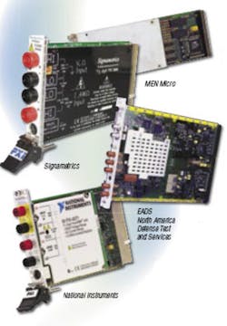
Many of the VXI and PXI DMMs cur- rently available are included in the com- parison chart accompanying this article. The various models can be grouped by price, performance, and functionality. Tee Sheffer, president of Signametrics, explained the situation: “Customers shopping for 5½-digit DMMs usually are looking for the lowest price while those considering 6½ or 7½ digits are looking for performance. However, in either case, a versatile DMM can reduce the size and cost of a test system by doing the job of two or three other instruments.”
A good example of a comprehensive DMM is the Signametrics Model SMX2064. As the chart shows, this is a 7½-digit DMM for use in a PXI system. In addition to the basic DC/AC V and I capabilities, it also provides 6-wire guarded resistance; extended resistance range to 5 GΩ; AC peak-to-peak, crest factor, and median value; leakage; RTD and thermocouple temperature; charge-balance and in-circuit capacitance; and inductance measurements, threshold voltage, and source functions.Alternatively, the company’s Model SMX2060 has the same AC/DC V and I as well as resistance measurements but without the system-level features. The strategy of offering separate comprehensive and basic models with the same DC/AC V and I measurement specifications is followed by other vendors as well. For example, the NI Model 4072 6½-digit DMM adds capacitance and inductance measurement capability to the basic functionality of the Model 4070.
Similarly, the ASCOR Model 3802-1004 is complemented by the comprehensive 3802-1005 that adds capacitance, inductance, 6-wire ohms, frequency, duty cycle, period, peak-to-peak, median, and crest measurements. The Model 3801 DMM has the same basic specifications as the 3802 but is implemented on a VXI-compatible carrier board that can accept one mezzanine (M) module.
More than 200 types of M modules are available from several suppliers and represent an economical approach to achieving high functional density in a custom test system. M modules comply with ANSI/VITA 12-1996, are approxi- mately 150 mm × 50 mm in size, and use a fast 32-b bus for transferring commands and data.
DMM Operation Dual-Slope ADC Lower cost DMMs with lower resolution and generally lower accuracy most likely use a dual-slope integrating ADC. Suitable for a 3½- or 4½-digit instrument, integrated versions of these ADCs typically are specified as providing 12-b to 16-b resolution. The ratio N of octaves to decades is given by N = 1/Log (2) = 3.32193. Using this conversion factor, 12 b/3.32193 = 3.6 digits, 16 b/3.32193 = 4.8 digits.
Integrating ADCs have been used for decades in low-speed, high-accuracy, and high noise-rejection applications. A dual-slope version integrates a current proportional to the input voltage for a fixed time period. A known, accurate current then is used to discharge the integration capacitor to zero while acounter times the discharge process. The discharge time is proportional to the average value of the input voltage.
Although second-order effects limit the precision of this direct implementation, dual-slope ADCs have the major advantage of rejecting AC line noise if the integration period, termed the aperture, is set equal to a multiple of a power cycle period. Typically, this is 16.66 ms (60 Hz), 20 ms (50 Hz), or 2.5 ms (400 Hz). The power frequency does vary a small amount, so better accuracy can be achieved by integrating for tens of cycles rather than for only one or two.
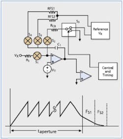
One variation on the dual-slope theme is a so-called charge-balancing ADC. In this technique, shown in Figure 1, the discharge current is applied in small bursts during the integration period. The effect reduces the total stored charge and consequently the effect of the integration capacitor’s dielectric absorption. Because much of the discharge process already has been accomplished before the integration period ends, the remaining charge can be removed more quickly and accurately. The measured value is proportional to the total of the applied burst periods and the final ramp-down time.
Another dual-slope variation, sometimes combined with charge balancing, is the multislope ADC. In a high-resolution, dual-slope ADC, the difference in voltage levels associated with successive time increments during discharge becomes extremely small. To avoid this accuracy limitation, the multislope architecture uses a succession of conversion stages.
The first stage may convert the input to a resolution of 6 b, for example. The output of this stage is subtracted from the input and the resulting residue amplified and applied to the input of a second stage, and so on. If the principle is carefully applied, multistage integrating ADCs can improve resolution by a decade or more beyond that of a basic dual-slope device.
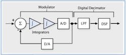
Sigma-Delta ADC DMMs with 6½- or 7½-digit resolution often use sigma-delta ADCs. A typical single-bit implementation, shown in Figure 2, accomplishes noise reduction in two ways. First, by using a high oversampling ratio, digitizing noise is spread over a bandwidth much greater than that of the input signal. When the output bit stream is decimated by the converter’s low-pass filter, most of this noise is eliminated.The second effect is more subtle and inherent only in this type of ADC. Because the loop filter within the modulator has more gain at low than at high frequencies, low-frequency noise is further reduced. This effect is termed noise shaping and leads to 24-b (7-digit) resolution being readily available in commercial ADCs. In addition, semiconductor sigma-delta converters tend to be low cost because of their digital nature.
While an ADC offers the resolution required by a 6½- or 7½-digit DMM, it may not provide a competitive reading rate, for example. The detailed design of a high-resolution DMM entails attention to many conflicting trade-offs, and each manufacturer has developed its own proprietary solutions.
For example, according to the Signametrics website: “Newly available technologies allowed [our] engineers to develop and implement…advanced features and superior speed and accuracy….”
Agilent’s latest DMM advances are in benchtop models such as the 34410A and 34411A. The company’s website explains, “Using a new A/D technology, the 34410A achieves an impressive 10,000 readings a second at 5½ digits….” Similarly, NI refers to“delivering measurement throughput rivaling higher resolution DMMs costing thousands of dollars more.”
All these statements pique the interest of design engineers and technicians who need to make fast, precise measurements. In the case of NI’s PXI-4071, a major ingredient is the use of a digital signal processor (DSP) to perform functions traditionally accomplished by other means. Because the DSP can perform a wide range of operations on the basic data samples, many DMM design compromises have been avoided.
For example, AC coupling is used to block the DC component of a waveform, but good low-frequency response requires a large value capacitor and its attendant charging time. The PXI-4071’s DSP calculates AC rms directly from the data samples and rejects the DC value. A conventional AC coupled mode also is available with improved sensitivity for measuring small AC signals riding on a large DC level.
The input attenuator is a 10-MΩ design to reduce power dissipation on high-voltage ranges. However, a 10-MΩ attenuator typically cannot achieve the bandwidth of a 1-MΩ design. An active bootstrap partially corrects the 10-MΩ frequency response, and the DSP provides the final compensation. In addition, the DSP accomplishes calibration and linearization of the combined high-speed ADC and custom sigma-delta design that forms the proprietary FlexADC at the heart of the DMM.
In a low-frequency sigma-delta converter, the digital output filter often is designed to have nulls at multiples of the AC power frequency. In the Analog Devices AD7719 dual sigma-delta ADC, for example, an integral phase-locked loop (PLL) provides programmable clock rates that determine the location of the filter’s nulls.
The PXI-4071 has three noise-rejection modes. In the normal mode, nulls appear at multiples of the reciprocal of the aperture time. For example, selecting a 16.66-ms aperture time will result in very narrow and deep nulls at multiples of 60 Hz.
A second-order mode produces somewhat wider nulls at two times the aperture reciprocal. In other words, setting the aperture to 33.33 ms creates nulls at 60, 120, 180…Hz. However, because the nulls are wider than in the normal mode, noise rejection is more effective for frequencies slightly different than these precise values. A third high-order mode rejects all frequencies above about 46 Hz by at least 110 dB.
In addition to the modulator section that generates a high-speed bit stream, sigma-delta converters also require an output filter to decimate the bit stream. NI designers have used a DSP to perform the digital filtering but also have applied it to many other functions within the DMM. The three noise rejection modes result from different weighting applied to samples by the decimating filter.
Because so many functions are accomplished via the DSP, it is relatively straightforward to make the actual digitized samples available. The point here is that, in general, the samples have not been combined or corrupted by a process traditionally performed near a DMM’s input, such as true rms conversion or AC coupling. In addition to its DMM functionality, the PXI-4071 also offers a 1.8-MS/s isolated digitizer mode.
This discussion of notable aspects of the PXI-4071 is not meant as an endorsement but rather to indicate that significant changes have occurred to the traditional high-resolution DMM architecture. NI has followed up its printed claim of superior performance with a white paper describing the technology that was used.
To View PXI/VXI DMM Comparison Chart Click Here
Summary
The answers to a few basic questions will help to characterize the DMM you need for your new test system. A good place to start is with resolution, accuracy, and throughput. All the products in the comparison chart provide a minimum of five- to six-digit resolution, at least 0.02% DC V accuracy, and from 10 to 100 readings/s. The choices narrow significantly if you need more than seven digits, 0.002% accuracy, or a faster reading rate.
Another set of questions relates to your specific application. Do you need to measure parameters other than V, I, and perhaps resistance? If you don’t need to now, will you in the future? The answer to these questions determines if you need a basic or more comprehensive DMM.
The level of DMM performance you select really can make a great difference to your final test system design. Signametrics’ Mr. Sheffer described a typical automotive application that required the accurate measurement of a few DC voltages, the capture of voltage transients from fuel injectors, and the measurement of fuel-injector solenoid inductances.
“Measuring the DC voltages is not difficult,” he explained, “but it takes good triggering to capture the fuel injector transients and fast inductance measurements to keep the test time short. The capacitance measurement function tests the shock sensor while the DMM’sbuilt-in pulse generator outputs a burst of pulses to test electric motors.
“We see few applications that use more than 30% of the functionality of our DMMs,” he continued. “However, each application uses a different 30% than the previous one. You have to have a broad range of capabilities to address a major fraction of the applications even if no one application uses all the capabilities.”
Reference 1. Understanding the NI PXI-4071 7½-Digit FlexDMM Architecture, National Instruments, 2004.
January 2006


