An emulation strategy can help you incorporate new test instruments as build standards are upgraded.
Overcoming test-equipment obsolescence is paramount in military and aerospace applications where test systems are supporting equipment with a service life of more than 20 years. However, replacing one or more obsolete instruments in a test system can have major consequences for the deployed Test Program Set (TPS). Even if a form, fit, and function replacement is made, a TPS or system software rewrite generally is inevitable.
Technology Insertion for Legacy Systems (TILS) addresses this problem across a wide range of ATE platform architectures and instrument obsolescence issues from single-instrument upgrade to complete automatic test system replacement. It also can be applied to systems incorporating low-level TPS programming such as BASIC language test programs with embedded instrument codes, graphical systems such as LabVIEW or VEE, or signal-based systems such as ATLAS. The capability to use the same solution across all test programs regardless of their development environment provides a powerful tool for managing obsolescence on ATE systems over the entire life cycle.
TILS uses resource emulation to translate instrument commands in real time to emulate the original system. A key architecture decision is identification of the communications interface from which the commands will be intercepted. Examples include any communications bus such as GPIB, RS-232, and Ethernet or low-level I/O drivers such as VISA or VXI. Higher-order software interfaces also can act as intercept points. But the higher the interface, the less universal the solution.
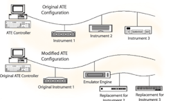
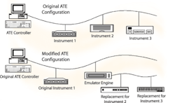
Figure 1 shows that there are no real constraints on the form of the new instrumentation inserted into the system. Examples of instrumentation could be smaller subsystems such as PXI or LXI or, in the future, synthetic instrument components.
Instrument Selection
The process of instrument selection comprises identification of the original instrument functionality subset that is to be replicated, selection of the replacement instrument(s), and integration of new instrument(s) onto the platform. Although these steps are listed as distinct activities, usually there will be overlap and interdependency among them.
Tools such as VISA Spy or GPIB Capture can help catch and correctly interpret the information contained in the interface traffic and provide an analysis report. A particularly useful format identifies each instrument and the direction of the data associated with it, timestamps the data, and organizes activity in a chronological order. This format helps to profile each instrument for replacement and captures potential interdependencies among instruments.
Combining this information with a statistical summary of bus data can characterize each instrument and its involvement within the ATE. This is possible without examining the original test programs and suitable for ATE users who do not have the original test programs or do not own the intellectual property rights (IPR) to their test programs. Where full visibility of the TPS source is available, valuable data regarding the actual use and timing requirements of the existing system can be provided.
This information may indicate that test programs do not use the full capability of the installed instrumentation. If it is not possible to find a current instrument with the full capability of the original instrument, it may be possible to select an instrument with reduced functionality.
An envelope initially is placed on the new instrument corresponding to the capability limits of the original instrument. However, the ATE performance specification normally offers a subset of this envelope, and examination of the actual instrument performance in the ATE system often forms part of the functionality bounding process.
Sometimes the instrument requirement can be constrained further by omitting any functional capability offered by the automatic test system performance specification but not used by any existing test programs. The performance specification of the automatic test system must be degraded accordingly.
Identifying unused functional areas can be a time-consuming process, especially when there are many test programs. Automated searches can help by identifying usage of original instrument commands in test-program executables.
Resource Emulation
When developing emulators for obsolete instruments, a number of key architectural decisions must be made:
� Where within the test system architecture should instrument emulators be located?
� What functional components are required?
� What instrument-specific information should the emulator contain?
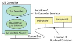
In Figure 2, the logical components of a typical test-system are shown in simplified form. Within this structure, instrument emulators might be positioned somewhere between the test executive and the device driver software (in-controller) or at the bus interface level (bus level); the emulator has its own presence on the bus.
In-Controller Emulation
Instrument emulators located within the original controller minimize the extent of physical change required to the test system and are well suited to memory-mapped instruments such as VME or VXI register-based instruments. However, this approach has its limitations:
� The controller/device driver may not provide the software hooks that this style of solution requires.
� This style of solution is platform specific and needs a different implementation for different makes and models of controllers.
� If configuration or maintenance programs and activities bypass the test executive and the emulation layer, this approach is unsuitable.
Bus-Level Emulation
An emulator placed on a test system bus as a one-for-one replacement for the original instrument provides a bus-level emulation of that instrument. This approach does not lend itself well to emulating instruments using memory-mapped control schemes.
For instruments controlled using a message-based control scheme such as GPIB, RS-232/422, or Ethernet, it produces emulators that are completely independent of the characteristics of the test system controllers. The implications of this are significant. Once developed, an emulator for a given obsolete instrument can be used as a replacement for that instrument in any test system.
Bus-level emulation generally requires an additional computing platform to host the emulation with a local bus for both the computing device and the associated instrumentation. In combination, the emulator host and the new instrumentation can be regarded as a composite instrument.
It is possible to use the original automatic test system controller as the emulation platform running as a multitasking platform with three buses: the original bus controller, a terminal, and a new bus controller to the new instrument.
Command Translation
The most basic form of an instrument emulator is a command translator. This emulator contains information about the command sets of the original instrument and its replacement and how to effect equivalent instrument behavior. Functionality for mapping parameter formats also can be required. In addition, when the original and replacement instruments have different reset states, the emulator can be required to select specific instrument configurations in response to relevant reset commands and bus operations.
This approach is effective when original and replacement instruments have similar command structures but support different command syntax. For example, if an operation has a logical predecessor which the original instrument performed automatically but which the replacement does not, a command mapping can ensure this operation is explicitly invoked in the replacement. If an original instrument automatically enabled an output when the associated level was set, then both a level-setting command and an output-enable command could be associated with the original instrument�s level-setting command.
However, differences in the command interfaces can result in unmappable commands. For example, there may be differences in the length of time for which information associated with a given command persists within the instrument. The effects of an original instrument command may rely on information carried within a previous command. If that information does not persist in the replacement for as long as it persists in the original, then it may be impossible to form a set of replacement instrument commands to effect the corresponding change.
For example, in one instrument, enabling and disabling modulation may be combined with selection of modulation type with possible parameters of AM, FM, and OFF. In an equivalent instrument, the two actions might be independent. A modulation state command might exist with parameters ENABLE and DISABLE and a distinct modulation type command with parameters AM and FM.
With the first instrument, information about the most recently selected modulation type is lost when modulation is disabled. With the second instrument, that information persists when modulation is turned off. Unless another modulation type command is received, the modulation type will be unchanged when modulation is re-enabled.
If the first instrument is used to replace the second, a command sequence equivalent to the original instrument�s modulation state command with ENABLE selected cannot be constructed using only the command-translation approach. This is because relevant state information is not held independently within the replacement instrument. The only effective solution is to maintain a full state model of the original instrument within the emulator.
State Modeling
When an emulator contains a state model of the original instrument, all aspects of the original instrument�s behavior will be in the state model of the emulator. This allows commands to the replacement instrument to be formed using complete knowledge of the configuration of the original instrument.
In the extreme case, the original instrument state model would be updated when each original instrument command is received. Then all the commands required to put the new instrument into a comparable state would be issued.
In practice, similarities between the original and replacement instruments can be exploited to reduce the number of replacement instrument commands sent. For example, if the only effect of an original instrument command is to set an output level and the replacement instrument provides a similar command, then the emulator can implement a direct mapping between the two.
An emulator needs to store the following instrument-specific information:
� An entity for each independent element of original instrument state.
� Information about interdependencies between these entities. For example, a source instrument might automatically reduce a high output level when a high frequency is requested. The state model must take similar action. The information that defines such changes to other entities within the state model can be regarded as a property of the entity itself.
� Information about how original instrument commands affect the state model.
� Information defining the commands exported by the instrumentation management system that are to be associated with changes in the state model. This information can be represented as properties of the state entities.
A state-modeling scheme also allows compensation within the emulator for some of the other ATE modifications that might accompany instrument replacement. For example, when replacing an obsolete high-frequency signal generator, for physical reasons it might be necessary to locate the replacement at a different position to the original. If a cable length changes because of this, it will be necessary to compensate for the resulting cable losses. One way to do this would be to apply a frequency-dependent offset to the level requested within the emulator.
Timing Considerations
Specific instrument timing requirements of existing test programs can be a concern. If a replacement instrument makes a measurement slightly earlier than the original or a source instrument takes slightly longer to settle, then the integrity of the tests may be compromised. For that reason, the framework must store timing-compensation information.
Various timing-compensation mechanisms are listed:
� Pre-Execution Delays�When there is concern that the replacement measurement instrument takes readings earlier than the original, a delay executed by the emulator before processing the command can be used to compensate.
� Bus Hold-Offs�Some bus types provide features that can temporarily suspend activity on the bus controller. Such features can be useful when the replacement source instrument takes longer to produce an output than did the original. A bus hold-off can be used to suspend controller execution of the test program while the output settles.
Another concern is that the emulator releases the bus more quickly than did the original instrument, giving previously configured source instruments less time to settle. When that occurs, a bus hold-off can be inserted as a means of compensation.
As a practical matter, timing considerations are significant in only a small proportion of instrument replacement cases. As a result, it is not necessary to incorporate characterization of all aspects of instrument timing into the process of emulator production routinely during development.
Rather, timing disparities should be allowed for in the emulator design and added as a configuration activity during integration on an as-needed basis. It is the intertiming with other equipment of the system that causes issues and not any specific instrument times.
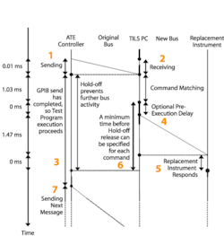
Figure 3 shows various activities as a function of time and highlights the effect of the timing compensation on a TPS using the TILS emulation technique.
1) The TPS sends the old instrument command out on the bus.
2) The emulator reads the command faster than the original and releases the bus with hold-off.
3) The TPS continues and performs any internal delays and calculations until a new bus command is required when the emulator hold-off prevents further TPS processing.
4) After receiving the original commands, the emulator sends commands to the new instruments following an optional pre-execution delay.
5) The new instruments do their stuff (technical software term).
6) The emulator can use features such as operation complete or historic timing information to release the hold-off.
7) The TPS now can continue with its bus activity because hold-off is released. At this point, the TPS has been synchronized with the valid signal state of the new instrument. The TPS does not proceed when the signal is not ready and does not measure until a signal is ready.
TPS timing considerations are taken into account by ensuring that the TPS is always synchronized with valid signals from the new instruments and that any measurements are taken on stable signals.
Integration
A TPS that relies on inherent timing of the ATE controller with instrumentation to measure transient events may not be supported by this approach. There may be other anecdotal evidence that an issue exists, such as comments from expert users identifying tests that have never worked or results that are just ignored.
The following questions can help to identify these situations:
� Does the TPS work across machines?
� Does the TPS work in the debug/release mode?
� Is the TPS trying to measure transients?
� Does the TPS fail occasionally?
The software-related aspects of integration provide confidence in the quality of the emulation. They also highlight whether there is a need for timing-compensation features and hold-offs.
In general, the process follows the format of running test programs on modified and unmodified test systems and verifying that the same results are obtained. This is where a bus-analysis report can be very useful. It usually is necessary to exercise only the functional components of test programs given that diagnostic routines generally are less demanding on instrumentation, especially in their timing aspects.
The criteria used to select the test programs to run are determined on a case-by-case basis. In some cases, it may be practical to run all affected test programs. In others, known similarities or knowledge about the extent of instrument usage can reduce this number to a representative subset. In facilities with multiple ATE, the same TPS and system software can run on both the original and modified ATE, allowing field trials to be conducted as part of a normal maintenance cycle and reducing the need to integrate all TPS.
Summary
The TILS approach addresses the problem of instrument obsolescence in test systems. The flexibility of the technique enables users to incorporate new test instruments without further test-program investment as build standards are upgraded.
Using TILS results in three important benefits. Obsolete instrumentation can be replaced with no changes to the logic of existing test programs. Changes in appearance or layout of the test system may make modifications to on-screen user instructions desirable, but usually these are not essential.
Secondly, future obsolescence of the chosen replacement instruments can be managed using current techniques built into the emulator�s instrument management system. Finally, special-to-type instruments often can be emulated using multiple general-purpose instruments in combination.
The solution primarily lends itself to message-based bus-type applications using defined software interfaces. For example, GPIB and RS-232/422 buses and the VISA driver layer for VXI instruments have been successfully implemented.
With TILS, obsolete instruments in major test systems can be replaced with only occasional TPS changes, demonstrating its practicality in solving real-world problems while maintaining existing TPS support. The technique has been used for more than 1,000 test programs from board- to LRU-level testing. TILS allows effective obsolescence management increasingly needed to keep test systems operational well past their anticipated service life.
About the Author
Chris Gorringe is a lead technical consultant at EADS Test & Services. He has more than 20 years of experience in pioneering test technology in international scenarios for the test and measurement industry. EADS Test & Services, 29-31 Cobham Rd., Ferndown Industrial Est., Wimborne Dorset BH21 7PF, e-mail: [email protected]
FOR MORE INFORMATION
on TILS
www.rsleads.com/606ee-183
June 2006


