A new concept can execute the same boundary scan test pattern on various ATE systems without modification.
Boundary scan is well established and widely used for various board- and system-level test and in-system programming applications. These applications typically include connectivity tests between boundary scan-capable devices and so-called cluster tests to verify connectivity to memory and logic devices that don�t provide boundary scan capabilities, referred to as non-boundary scan devices.
The testability and the achievable test coverage are UUT-specific and depend on the level of boundary scan implementation.1,2,3 Especially in production test, measures are taken to extend the boundary scan test coverage by using tester resources connected to peripheral I/O on the UUT.
In the recent past, integration of third-party boundary scan tools was popular in board-level production test equipment such as in-circuit testers. Often times, such integrations provide little benefit over stand-alone boundary scan systems. While some of those solutions offer improved test coverage by combining boundary scan and ATE resources, they introduce new problems like skewed test-coverage statistics and very limited portability.
Boundary Scan Systems
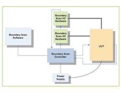
A typical stand-alone boundary scan system consists of a PC running boundary scan software, a boundary scan controller, a power supply to power the UUT, and cabling to connect the UUT to the boundary scan controller and the power supply. Such a system supports various test and in-system programming applications using the test resources available on the UUT including interconnect test, memory and logic cluster test, flash programming, and PLD programming.
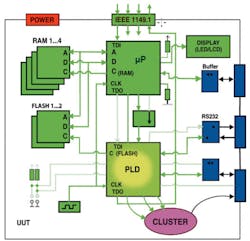
Some boundary scan systems provide tools to extend the test coverage by including non-boundary scan circuitry typically not testable with an automatically generated test pattern. Such applications include the verification of an oscillating clock signal, test of switch or jumper settings, and illumination of optical indicators with operator feedback (Figure 1).
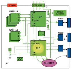
By complementing the UUT�s on-board test resources with external test channels (Figure 2), the test coverage can be extended to the UUT�s interface circuitry on peripheral connectors. Especially when using external access to test points on nets otherwise inaccessible via boundary scan, the diagnostic output can be improved.
Even though both test coverage and diagnostics improve when boundary scan I/O tester hardware is used, new problems are introduced with this method. When boundary scan tests are developed considering just the UUT�s test resources, then all test-coverage statistics are based on the number of nets and the number of pins on the UUT only. By adding tester resources to the boundary scan setup, however, the tester resources themselves are included by automated test coverage analyzers, skewing the statistics.
For test generation, these boundary scan I/O tester resources are merged with the UUT net list. Then test programs are generated based on this merged net list. This causes the number of nets and pins evaluated during the test-coverage analysis to increase. The result of the test-coverage analysis does not represent the UUT anymore but rather the combined UUT and tester I/O configuration.
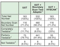
Table 1 provides an example of the impact of this combined net count on test-coverage statistics for a boundary scan interconnect test. Such a skewed test-coverage statistic is misleading when you want to analyze the suitability of boundary scan for a specific UUT and the impact of added I/O resources.
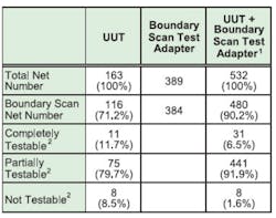
2) Nets Connected Through Serial Resistors Counted as One Net for Testability Statistics
Since the boundary scan I/O resources are merged with the UUT net list for the purpose of test-program generation, the developed test pattern only can be executed on this tester configuration. As soon as the number, the order, or the type of boundary scan I/O resources changes, the test pattern must be modified accordingly. This drastically reduces the portability of the boundary scan test programs.
A third problem of adding boundary scan I/O resources to the tester setup, although less problematic for most applications, is the increased length of the scan chain. Additional TCK clocks required to shift the test pattern through the boundary scan I/O module result in longer test execution time and reduced effective test throughput. However, such I/O modules can be connected to a separate boundary scan chain, reducing or eliminating the impact on test execution time.
Integrating Boundary Scan
A stand-alone boundary scan system may use boundary scan I/O resources to extend the test coverage on the UUT�s interface circuitry. An integration of the boundary scan tools on an in-circuit tester, utilizing the nails in the fixture to contact nets to improve testability and diagnostics, requires the development of additional test programs. It would be desirable to run the same test programs on the stand-alone system and on the integrated solution to reduce test development time and maintenance.
The principle is the separation of shift vectors and parallel I/O vectors. Test programs include both the test pattern for the UUT�s boundary scan chain and the tester�s I/O resources. However, the test pattern for the I/O resources is independent from the actual tester hardware.
The same I/O test pattern is used for boundary scan I/O modules, parallel I/O modules, in-circuit test nails, or other ATE I/O resources. When the test programs are ported to the various ATE, the actual tester I/O resources are mapped to the I/O test pattern by means of a tester configuration and a wiring list.
Figure 3 shows a tester configuration with a boundary scan controller and additional tester I/O hardware. The boundary scan controller provides access to the UUT�s JTAG test access port as well as a trigger interface to the tester I/O hardware.
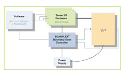
The I/O hardware is controlled directly by the software. The test pattern is transferred to and from the I/O resources over the host bus interface rather than through a boundary scan chain.
Access to the UUT�s peripheral interface connectors with the hybrid scan I/O resources provides the same improvements in test coverage that can be achieved with boundary scan I/O modules that use scan chain access. However, since the product�s I/O pattern is not described as being part of a boundary scan chain, but rather as a parallel I/O pattern, the test programs for such a configuration can be ported to use other ATE I/O resources without any modifications in the test program. Since the I/O pattern is independent from the UUT boundary scan description, the test coverage statistics are not distorted.
Table 2 shows the difference in test-coverage statistics when using boundary scan I/O modules merged with the UUT vs. the implementation of the hybrid scan concept. Considering UUT and tester I/O resources separately ensures accurate and UUT-oriented test coverage statistics.
2) Nets Connected Through Serial Resistors Counted as One Net for Testability Statistics
The concept is based on a hybrid test pattern, combining serial access through the UUT�s boundary scan chain and parallel access through tester I/O resources. These tester I/O resources should be individually programmable as input, output, or three-state.
Voltage-level programmability and considerable driver strength, combined with over-current protection or other safety measures, are desirable. The boundary scan test programs using HYSCAN I/O resources do not need to take into consideration the physical realization of these I/Os.
For the test pattern, it does not matter whether the I/Os are provided via parallel I/O modules or tester channels on an in-circuit tester, for example. The test program is generated based on the UUT net list and a description of which nets are accessible to tester I/O resources. Then, a tester configuration file and a wiring list provide information about the actual assignment of tester I/Os to nets on the UUT. Only the tester configuration and wiring list need to be adapted to the actual test setup, not the test program itself.
Figure 4 shows an example boundary scan project that uses tester I/O resources. The project includes three tester configurations for a stand-alone boundary scan system, an in-circuit test system, and a functional test system.
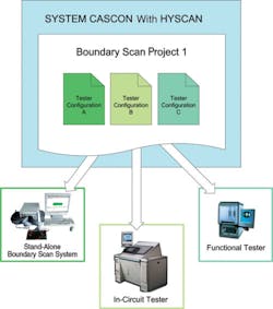
Figure 4. Example Project With Three HYSCAN Tester Configurations
Only one set of test programs is required. The same tests can be executed on all three test systems because the mapping of the I/O pattern in the test program is controlled by the respective tester configuration.
In this example, the stand-alone boundary scan system includes a PXI boundary scan controller, a PXI digital I/O module with 192 channels, a PXI power supply module, and a PXI I/O module. The 20 test channels from the I/O module are connected to a peripheral interface connector on the UUT. The test program controls both the UUT�s scan chain and the I/O module�s test channels.
On the in-circuit test system, the UUT�s peripheral interface connector is accessed through a test fixture. The test channels are realized by the in-circuit tester�s I/O resources. The same test program that had been used on the stand-alone boundary scan test system now controls the UUT�s scan chain and the in-circuit test channels.
The functional test system provides access to the UUT�s peripheral interface connector through parallel I/O modules connected to the tester�s I/O resources. In this configuration, the same test program used on the stand-alone boundary scan system and the in-circuit tester is applied.
Control of the I/O resources of the various test systems is realized through hybrid scan drivers, which interface the boundary scan software and the tester configuration with the ATE software/hardware.
Conclusions
HYSCAN introduces another approach of integrating boundary scan tools in various board-level ATE. It provides portability between various test channel types and accurate test results and test coverage statistics. UUT and tester I/O resources do not have to be merged for the purpose of test-program generation, and developed boundary scan tests are independent from the test adapter type and the test system they are executed on. At this time, HYSCAN is limited to digital I/O although it provides for expansion into mixed-signal testing.
References
1. Parker, K.P., The Boundary Scan Handbook, 3rd Edition, 2003.
2. Design for Testability Guidelines for Boundary Scan Test, GOEPEL Electronics White Paper, 2005.
3. Ehrenberg, H., and Muench, N., �Leveraging Boundary Scan Resources for Comprehensive Cluster Testing,� Proceedings of Board Test Workshop, 2004.
About the Author
Heiko Ehrenberg is managing director of operations at GOEPEL Electronics LLC. After graduating from the University of Applied Sciences at Mittweida, Germany, in 1996, he was employed by GOEPEL electronic GmbH in Jena, Germany, as an application engineer for JTAG/boundary scan. In 1998, Mr. Ehrenberg transferred to the company�s U.S. subsidiary and was promoted a year later to his current position. GOEPEL Electronics LLC, 9600 Great Hills Trail, 150W, Austin, TX 78759, 512-502-3010; e-mail: [email protected]
July 2006
About the Author
Comment About the Article
To join the conversation, and become an exclusive member of Electronic Design, create an account today!

Leaders relevant to this article: