Required Amplifier Power in Automotive Radar Pulse Measurements
What will keep your brakes from failing or your airbag from deploying the next time you cruise past an airport?
For many years, automakers have performed electromagnetic compatibility testing of automobiles before their release to consumers. However, as the electronics content of vehicles becomes greater every year, it expands the potential for component or system failure caused by external sources of electromagnetic radiation.
One challenge has come from commercial and military airport radar systems that operate at frequencies from 1.2 to 1.4 GHz and 2.7 to 3.1 GHz. Cases have been reported in which vehicles near airports and military bases suffered degradation or even failure of critical vehicle systems including braking controls and airbag deployment. As a result, Ford Motor Company and General Motors Worldwide (GMW) have introduced sections in their immunity standards for component testing when exposed to radar pulses, such as those at the 600-V/m level.
Generating pulsed RF signals at such an elevated power level and frequencies for EMC testing requires the use of high-power amplifiers and very-high-gain antennas. Since the cost of RF power escalates with increasing frequency, it is important to subcontractors and test houses that the amount of RF power required be as low as possible.
The principal method of making these measurements is with an absorber-lined shielded enclosure (ALSE) and a test bench with a metallic ground plane. However, there is an alternate method using a reverberation chamber (RVC).
The Standards
The standards that guide the EMC testing of automotive components for GMW and Ford are GMW 3097 and ES-XW7T-1A278-AC, respectively. The radiated immunity test set for each one is based on ISO-11452-2.
The previous version of the GMW and Ford tests considered only one severity level, 600 V/m, and required 50 3-�s pulses within a 1-s period at a repetition rate of 300 Hz. At present, GMW still requires the 50 pulses within a second, but Ford removed this specification, leaving just the pulse repetition rate of 300 Hz and pulse duration of 3 �s.
GMW and Ford specify testing from 1.2 to 1.4 GHz, and Ford requires testing from 2.7 to 3.1 GHz as well. Recent revisions by Ford eliminated the need for a metallic ground plane, replacing it with a test bench that has a low dielectric constant and height of 1 m �50 mm.
In radiated immunity testing within an anechoic chamber, the antenna is a critical part of the setup because it converts the guided electromagnetic energy in the cable to unguided or radiated energy. The antenna must be highly directive and well matched to produce very high gain.
EMC engineers might be tempted to use the well-known far-field equation to estimate field strength. A 600-V/m field can be generated at 1 m from the EUT with an RF amplifier producing 200 W and a horn antenna with 15 dBi of gain. However, this equation is not valid because the measurements are being conducted in the extreme near field. Furthermore, the presence of a metallic top dramatically influences the field-generation and field-strength measurements.
Tests conducted by ETS-Lindgren show that antenna gain decreases up to 4 dB in the near field. For measurements, a horn antenna with a small aperture is used to reduce power spreading. In the E-plane, corrugations are used to reduce spillover and side lobes, concentrating the power toward the front. Septums are used inside the horn to improve aperture efficiency.
Anechoic Chamber Test Results
In the test setup, calibration was performed in the CW mode because field probes cannot handle pulses without a correction factor. The test was performed from 1.2 to 1.4 GHz, and the software-controlled frequency sweep was set to achieve 600 V/m.
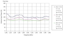
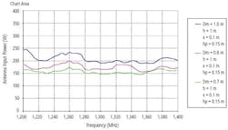
The field strength was measured with a field probe, and the forward and reverse powers were measured with a power meter. The cables were calibrated to account for their losses. The antenna input power required to produce a 600 V/m field at three distances between the antenna and the bench is shown in Figure 1. The results illustrate that it is possible to achieve 600 V/m with less than 250 W of RF input power to the antenna.
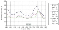
However, the ground plane produces dramatic differences between the power levels required to achieve 600 V/m in the two polarizations (Figure 2)In addition, the centerline of the antenna is only 100 mm above the metal ground plane so half of the radiated power illuminates the air under the bench.
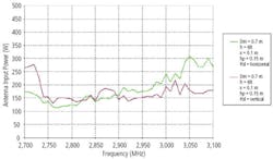
At the 1-m distance required by the standards, nearly 500 W is necessary to generate the required field in the lower frequency range. When testing using the higher-frequency horn antenna at 2.7 to 3.1 GHz, the antenna was moved to 70 cm from the test bench.
In the horizontal orientation, the reflection from the metal-topped bench assists the results. At the 70-cm distance, a 600-V/m field can be generated with about 200 W of RF power, but vertical polarization still requires more than 450 W of power to achieve the same field.
To minimize these differences and hopefully reduce the required RF power, the antenna was bore-sighted and tilted toward the probe. In a bore-sighted configuration, the power levels in both polarizations are similar, and 600 V/m can be accomplished with about 300 W of power (Figure 3).
Based on these test results, Ford amended its ALSE test procedure and test levels. For Band 6 (1.2 GHz to 1.4 GHz) and Band 7 (2.7 GHz to 3.1 GHz), the test table with a metallic ground plane has been replaced by a dielectric support, and the severity level has been reduced to 300 V/m for some types of equipment.
The Reverberation Chamber Alternative
Another way to make the measurements called for in the Ford and GMW standards uses an RVC for immunity testing. An RVC is a resonant cavity in which RF energy is injected and the power density available in the chamber creates the required test E-field.
A statistically uniform, isotropic, and homogeneous field is generated with a tuner, which changes the boundary conditions of the cavity during the measurement. The EUT is immersed in the test field so all orientations of the EUT are illuminated without the need for rotation. In addition, directional antennas are not required, and antenna location is not critical.
The trade-off with the RVC method is increased use of the amplifier vs. its potentially lower cost. Although Ford modified its test method for anechoic testing, the test methods when using an RVC remain unchanged for both the GMW and Ford standards.
Testing in an RVC is based on the statistical performance of the chamber, so several samples of the field in the chamber are required. The losses in the chamber that reduce power density are caused by the antennas, chamber surfaces, and the EUT. The energy fed into the resonant cavity takes some time to dissipate, which prevents RF from being switched very quickly.
The required 3-�s pulse duration can be achieved only in a heavily damped (lossy) chamber. Unfortunately, there is a direct relationship between increased chamber loss and the RF amplifier power required to generate the 600 V/m field. To overcome this limitation, the standards call for an increased pulse duration of 6 �s in an RVC to reduce losses.
Calibration and Loading Validation
While the goal when configuring an RVC is to generate a uniform electromagnetic field environment within a defined working volume, there always is some uncertainty. To accurately determine chamber uniformity and input power requirements, a one-time empty chamber calibration without an EUT and nonessential equipment must be performed. The antennas directly affect calibration, and any change to the antennas requires recalibration of the chamber.
Field uniformity is defined as a standard deviation from the normalized mean value of the maximum values obtained at each of the eight probe locations during one complete rotation of the tuner in discrete steps. For frequencies higher than 1 GHz, the minimum number of tuner positions is six. The standard deviation is calculated using the total data set and the data from each probe axis (X, Y, and Z). The average normalized maximum E-field is calculated during the empty chamber calibration.
A maximum chamber-loading verification is performed to determine the worst-case loading affects of an EUT on the chamber. The size and material of the EUT determine how much it will load the chamber.
To evaluate the field uniformity under a severe loading condition, another calibration run is performed with a significant amount of absorbing material installed, and the uniformity calculations are repeated. If either the field uniformity of the individual rectangular components or the field uniformity for all axes is greater than the allowed standard deviation of 3 dB, the chamber no longer meets the field uniformity requirements, and the amount of loading must be reduced.
The maximum chamber loading veri�fication generally must be performed only once but is dependent on the structure of the chamber. Any major structural modifications require the loading verification be repeated. Typical dimensions of an RVC are 4.80 m � 3.60 m � 3.05 m.
Before a test can be performed, the DUT must be proven not to load the chamber and affect the field uniformity. If the DUT causes loading effects, there is no longer enough energy to generate the desired field.
To determine any loading effects of the DUT, a load-check calibration is performed. The DUT and any supporting equipment are placed in the chamber during the calibration.
During the DUT load check, an eval�uation of the chamber-loading factor (CLF) is performed. If the average received power is within values determined by the empty chamber calibration at each respective tuner position and frequency, the CLF value is assumed to be 1. If it is not, the CLF must be calculated. If the DUT affects the field uniformity of the chamber, the empty chamber calibration must be repeated with the DUT placed in the chamber. All RVC results shown correspond to a CLF
value of 1.
Insertion Loss and Power Requirements
By performing a series of normalizations and averages for each field probe axis, an average normalized maximum E-field value is calculated, and the value is determined for each frequency during the empty-chamber calibration. The average normalized maximum E-field is the average of the normalized maximum of all the electric-field measurements at each probe position. It represents the expected amplitude of the chamber E-field, which is the value to which the chamber is calibrated. Field strength in the chamber will continually vary, but the average field strength over a period of time will remain relatively constant.
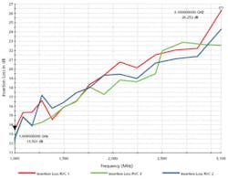
The average normalized maximum E-field determines the chamber power required to achieve designated field strengths. The average normalized maximum E-field tends to decrease as frequency increases. The empty-chamber calibration also produces an insertion loss value. Figure 4 shows the increasing insertion loss values over frequency for the same three chambers.
Insertion loss increases directly with frequency, which leads to the impression that chamber-loading effects are the cause. Greater loading can be caused by the EUT and auxiliary components or the chamber itself.
Considering that the EUT is not altered in relation to frequency for a given test run, the chamber appears to gradually contribute to loading. More specifically, the material lining the cavity of the chamber may contribute to loading effects at increased frequencies.
Absorption loss is a function of thickness and frequency for a given material, and in the three sample chambers, the lining material is galvanized steel. It may be possible to use an alternate material to minimize the effects of absorption at higher frequencies, but the compromise may be increased material cost.
Measurement Results
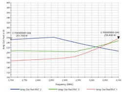
So, what effect does increased insertion loss have on the power required to produce the necessary 600 V/m. In the tests, slightly less than 185 W of power were required to generate 600 V/m at the lower frequencies and insertion loss was lower.
The requirements for the upper frequencies are shown in Figure 5. The trend of the curves deviates slightly from the initial frequency to the endpoint, but at the highest frequencies, nearly 260 W are required to achieve 600 V/m.
Not surprisingly, insertion loss plays a much greater role at higher frequencies. Based on the calibrated normalized maximum E-fields, the sample chambers indicated that a 600-V/m pulse can be generated using a 300-W amplifier.
Summary
The cost of RF power amplifiers is directly proportional to required output power. As a result, component suppliers and testing facilities benefit from having an accurate representation of the power requirements necessary to achieve a 600-V/m field. Actual test data, as shown in the conducted experiments, displays the achievement of the required GMW and Ford field strength and the power required to attain it, regardless of whether the ALSE or RVC methods are used.
For Further Reading
1. IEC 61000-4-3 Testing and Measurement Techniques�Radiated, Radio Frequency, Electromagnetic Field Immunity Test
2. GMW 3097, Revision 4, February 2004
3. FORD ES-XW7T-1A278-AC
4. EMC Requirements and Test�ing Chan�ges for RI114�Ford Motor Company, Feb. 24, March 13, and March 19, 2006
About the Authors
Kerby Gove is a project manager for EMC and RF test systems at Rohde & Schwarz. Mr. Gove has more than 10 years of experience in computer programming and wireless applications and five years of experience in the EMC field. He studied computer science, electrical engineering, and wireless communications technology at the University of Texas where he obtained a B.S.E.E. 469-713-5336, e-mail: [email protected]
Hans-Peter Bauer is a senior project manager for EMC test systems at Rohde & Schwarz. He has more than 12 years of experience in EMC test systems for commercial, automotive, and military applications. Mr. Bauer received his electrical engineering degree from the Fachhochschule in Mannheim, Germany. 469-713-5332, e-mail: [email protected]
Rohde & Schwarz, RF Test Systems, 8080 Tristar Dr., Suite 120, Irving, TX 75063
Vicente Rodriguez-Pereyra, Ph.D., is senior principal antenna engineer at ETS-Lindgren. He received a B.S.E.E., an M.S.E.E., and a doctorate from the University of Mississippi and formerly was on the electrical engineering and computer science faculty at Texas A&M University. ETS-Lindgren, Field Generation Group, 1301 Arrow Point Dr., Cedar Park, TX 78613, 512-531-6436, e-mail: [email protected]
August 2006
