Mixed-signal oscilloscopes (MSOs) solve a basic conundrum: Logic analyzers have a large number of inputs but offer no analog capabilities and typically are hard to use. In contrast, oscilloscope operation is intuitive, but scopes have no more than four channels. MSOs provide both analog and digital channels in a familiar scope format.
The MSO name was coined by Agilent Technologies, at the time part of Hewlett-Packard, when the MSO was introduced 10 years ago. This instrument integrated either two or four conventional scope channels with 16 logic-timing channels. Fortunately for today�s engineers and technicians, the MSO terminology has caught on.
For example, LeCroy offers the MS Series MSO option for the company�s WaveSurfer Xs and WaveRunner Xi product lines. Yokogawa doesn�t use special designations but simply refers to the Model DL9710L as a mixed-signal scope. Tektronix has adopted the MSO prefix as part of the model number. Just as the company has a TDS and a DPO series, now there is an MSO4000 Series as well.
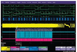
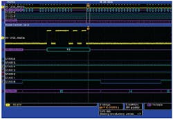
Other than similar terminology, what common set of features can a user expect to find across all brands of MSOs? There is remarkable similarity among products from the four major scope manufacturers, such as the wealth of display detail shown in Figure 1, but there are important differences as well.
Figure 1. Mixed-Signal Display With Digital and Analog Channels,
Serial Bus Decode, and Collapsed Bus
Courtesy of LeCroy
Striking a Balance
Vendors agree that an MSO is not a logic analyzer. For example, Chris Loberg, senior marketing manager at Tektronix, said, “Today�s logic analyzers can acquire more than 100 channels to address unique design challenges but may require hours to set up. In the case of an MSO, it�s important to recognize that for most engineers it is an instrument quickly deployed for important, yet simpler, design verification tasks.”
Clearly, 100 channels are too many, but how many digital channels do you really need? Agilent continues to provide 16, the same number as in the first MSO. Tektronix offers 16 and LeCroy 18 although LeCroy�s MS-500-36 option is a 36-channel version. Yokogawa has opted for 32 channels as standard.
Digital channels can be grouped as buses for display and triggering. A handy feature is the capability to include a given channel in more than one group. This allows you to compare timing of a number of channels to a common signal.
Viewing several related channels as a collapsed bus greatly simplifies the display of many simultaneous traces without losing information. Yokogawa provides a useful computed DAC function on a group of digital channels, producing a multilevel waveform representative of the successive digital bus values. Tektronix offers multichannel setup and hold verification across a parallel bus.
Serial bus decoding and triggering are important capabilities first made available in the DSOs on which MSOs are based. One or more scope analog channels can be used for this purpose on both the base DSOs and derived MSOs from all four manufacturers. Buses dealt with include I2C, CAN, SPI, UART, RS-232, FlexRay, and LIN. Not all types of buses are available from all vendors, and bundling of bus types within a single option varies by vendor.
LeCroy�s MS Series MSOs also can perform all the serial bus decoding and trigger functions from digital channels, as can Agilent MSOs. Yokogawa soon will have that capability for I2C and SPI buses. Tektronix doesn�t distinguish between MSO and DSO operation on this point.
Triggering across 20 or more channels is supported as are a number of state and pattern triggers. According to Agilent�s Infiniium 8000 Series datasheet, for example, “There are no limitations on the combination of analog and digital channels that can be used for a particular pattern or state trigger setting.”
However, a common feature of all four manufacturers� datasheets is a lack of details regarding the interaction between the digital and analog channels. Clear statements, such as Agilent�s, help define what you can and can�t assume.
Operation
While all MSOs provide valuable information about the timing relationships among digital and analog channels, there are a few operational limitations that you need to consider. MSOs are scopes with additional digital channels added: How completely the extra channels have been integrated makes all the difference.
Ideally, an MSO would offer at least 20 channels that performed as uniformly as possible. Analog channels require a sensitive preamplifier with a high input impedance and a fast, high-resolution ADC. Digital channels must have sufficient bandwidth and a fast comparator. The goal is to create an architecture in which the data signals existing after the ADCs and comparators are treated equally. The only difference should be the 1-bit resolution of the digital inputs vs. the n-bit resolution of the analog channels.
In today�s MSOs, digital inputs and analog inputs have different characteristics. The maximum allowable voltage ranges from �15 V for Tektronix to Agilent�s �40-V peak CAT 1. The CAT 1 qualification implies a transient overvoltage capability not included in Yokogawa�s unqualified �40-V rating. LeCroy�s MS-500 has a maximum
�30-V rating.
Input impedance also typically is not the same as an analog channel�s 1 M?. Tektronix specifies 20 k?, Agilent 100 k?//8 pF, and LeCroy 100 k?//5 pF. Yokogawa offers the 100-MHz bandwidth type 701980 pod with 1-M?//10-pF impedance. The 250-MHz type 701981 pod is specified with 10 k?//9 pF.
Bandwidth varies as well. Agilent and Tektronix specify the minimum width pulse that can be acquired: 1.5 ns for Tektronix and 2.5 ns for the Agilent Infiniium 8000 Series. These widths correspond approximately to 330-MHz and 200-MHz bandwidths, respectively.
LeCroy offers three MS Series versions. The MS-500 has 18 digital channels and 500-MHz bandwidth with a 2-GS/s maximum sampling rate. The MS-500-36 also provides 500-MHz bandwidth but a 1-GS/s maximum sampling rate and half the memory length when both 18-channel pods are used. A third model, the MS-250, has 250-MHz bandwidth, a 1-GS/s maximum sampling rate, and only 10 Mpoints of memory per channel vs. 50 Mpoints for the MS-500 and MS-500-36.
A variety of standard logic family thresholds is selectable, and you also can program custom threshold values as required. Only one threshold value may be selected per logic pod for Agilent, Yokogawa, and LeCroy MSOs. Tektronix supports per-channel threshold selection or programming.
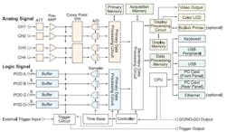
In addition to these specific hardware differences, all MSO architectures have a seam between the analog and added-on digital channels. A simplified block diagram identifies an MSO�s various parts but not details of their interactions (Figure 2). How much you notice the seam and what problems it causes will depend on the particular model of MSO and how you are using it. Many technical aspects could be discussed, but a few of the more fundamental are highlighted here.
Figure 2. Simplified MSO Block Diagram
Courtesy of Yokogawa
Click here to see larger image
Mixed Sampling Rates
For example, how does an MSO handle mixed sampling rates? If you are simultaneously displaying analog channels and digital channels, what happens when you increase the analog sampling rate to be greater than the maximum digital sampling rate? This problem is common to Tektronix, Agilent Infiniium, and LeCroy MSOs. Yokogawa�s DL9710L maintains the same maximum sampling rates for the analog and digital channels as well as a common 6.25-MW memory length across all channels.
MSOs always acquire the same amount of time for analog and digital channels. One way to make the operation of features like zooming appear consistent is to follow Yokogawa�s approach and simply run both digital and analog channels at the same rates and with the same memory lengths. Alternatively, if the sampling rates are different, so too will be the amounts of memory used.
Agilent�s Infiniium 8000 Series MSO samples digital channels at a maximum 1-GS/s rate and analog channels at either 2 GS/s or 4 GS/s. The 6000 Series MSO samples eight channels of one logic pod at 2 GS/s or more than eight channels at 1 GS/s. The 6000 Series shares memory between analog and digital channels, but the Infiniium 8000 does not. For both scope series, equal amounts of time are captured on digital and analog channels, and the relationship between analog and digital memory lengths is automatically adjusted as required.
In Tek�s MSO4000 Series, digital channels are acquired at a maximum 500-MS/s sampling rate. The MSO4104 has a maximum 5-GS/s analog channel sampling rate. The maximum memory length is 10-MW per channel regardless of type.
However, not all the digital memory length can be used at high time-base settings if analog channels also are being acquired. Only 1 MW of digital data can be acquired at 500 MS/s during the 2 ms it takes to fill the 10-MW memory associated with an analog channel running at 5 GS/s. Mixed-signal acquisition cannot use all of the 10-MW digital channel memory at sample rates above 500 MS/s.
LeCroy�s MS-500 Logic Pod inputs are sampled at a maximum of 2 GS/s. The WaveSurfer Xs and WaveRunner Xi, the host instruments for the
MS-500 option, can have analog channel sampling rates as high as 5 GS/s or 10 GS/s, respectively.
Were you to simultaneously display analog channels sampled at 5 GS/s and digital channels sampled at 500 MHz, what would you see? Answering this question requires a slight digression. Each of the four manufacturer�s MSOs combines changes in sampling rate, acquisition memory length, and horizontal magnification to arrive at a composite maximum time-base rate as high as 200 ps/div.
A 200-ps/div time-base setting corresponds to only one sample per division at a 5-GS/s rate. The other 99% of the waveform is interpolated. Newer DSOs that use XGA displays generally display 100 points per division at the highest time-base setting. On the basis of 100 points/div, the fastest unexpanded time-base rate for MSOs running at a 5-GS/s rate is 20 ns/div.
This time base corresponds to a 1,000-point acquisition or 800 points for Agilent because of the maximum 4-GS/s sampling rate. Longer acquisitions require more time to complete, naturally limiting the waveform update rate. When the captured data is compressed for display, the time-base rate must be scaled accordingly. For example, to display all of a 1-Mpoint acquisition made at 5 GS/s requires a 20-�s/div time-base setting. The waveform update rate under these conditions can never be greater than 5,000/s.
So, at a maximum 20-ns/div time-base setting, Tek�s MSO4104 digital channels will display 10 samples per division. Agilent�s Infiniium sampled at 1 GS/s presents 20 points. LeCroy�s digital channels and those from the Agilent 6000 Series sampled at 2 GS/s, 40 points and Yokogawa scopes at 2.5 GS/s, 50 points. A number of artifices such as interpolation or repeated sample values can be used to connect the real samples at this and faster time-base settings.
Skew Among Channels
All modern DSOs, including the major manufacturers� MSOs, allow the analog channels to be deskewed. Either by recalling probe- and channel-specific values or entering timing corrections manually, you can null differences in propagation delay across all four input channels and probes. In contrast, some MSOs do not support digital channel deskew.
According to Mike Hertz, field applications engineer at LeCroy, “Both the WaveRunner and WaveSurfer allow deskew control between the digital channels and analog channels with a resolution of 0.5 ps. Each of the analog channels has its own deskew control located in the channel menu. For example, the user could deskew channel 1 to +2.4 ns, channel 3 to -1.5 ps, and channel 4 to +100.5 ps relative to the digital channels.
“The digital channels are already matched and do not need to be deskewed relative to each other. Any variation in skew between these matched channels is negligible compared to the timing resolution with which the timing edges are acquired,” he explained.
Yokogawa�s Joseph Ting, product manager at the company�s Test and Measurement Division, said, “In the DL9710L, skew between logic channels is negligible. However, skew between the analog and logic channels typically is around 2 or 3 ns. As a result, the DL9710L has a skew adjustment feature that allows up to 80 ns of deskew at 10-ps resolution to align the analog and logic channels.”
Tektronix specifies skew among digital channels to be 1 ns typical although the channels are deskewed to a much tighter tolerance as part of the factory calibration process. This procedure ensures that the digital channels are aligned for both the acquisition and trigger systems.
In contrast, Agilent states 2-ns typical, 3-ns maximum channel-to-channel skew among digital channels. The user has the ability to adjust analog channel skew and the skew between the analog and digital channels but not among the digital channels themselves.
Channel-to-channel skew is important because it directly adds or subtracts from the timing relationships that actually exist among your digital signals. For example, if you are trying to understand a race condition in logic running at 100 MHz, the basic clock rate and all the signals derived from it are relatively slow.
However, a race is caused by differences in propagation delays and can easily be 1 ns or less in a 100-MHz system. If the digital channels probing the affected signals are themselves skewed by 1 ns or more, there�s no way you can troubleshoot the race condition. This is a basic limitation. Your most practical option is to use a couple of accurately time-aligned analog channels to investigate further.
Separate Acquisition Modes
The Tektronix MSO4104 provides a high-speed MagniVu acquisition system that automatically captures 10,000 points from each digital channel centered on the trigger event. Using this feature, you can examine logic channel timing in more detail, especially transitions that appear to occur simultaneously when sampled at 500 MS/s. The highest sampling rate is 16.5 GS/s or a sample every 60.6 ps.
If the 4000 Series digital channel propagation delay stabilities with time and temperature are sufficiently good, MagniVu becomes a remarkable tool for looking at signal drift. It can show relative signal timing changes in great detail.
MSOs simultaneously sample analog and digital channels on edges of an internal, asynchronous time base. This means that on slow time-base settings it always is possible that skew can make one digital signal appear to occur one complete time-base clock ahead of or after another. The chance of this occurring becomes less as skew is reduced. MagniVu can minimize this kind of confusion.
Additional troubleshooting insight would be available were MSOs to support external clocking. Logic state displays imply the existence of this mode. However, the state information typically is derived from timing data and not from a separate synchronous acquisition. The importance of small amounts of channel-to-channel skew becomes much less when state data is acquired synchronously than when timing information is acquired asynchronously because the states are settled when they are sampled.
Both the LeCroy WaveSurfer Xs and WaveRunner Xi accept an external clock signal on the auxiliary input. So, in theory, the MSOs based on these instruments could perform true state analysis. Yokogawa�s DL9000 Series scopes can use an external clock signal on channel 4 to qualify a state trigger formed by a combination of signals on analog channels 1 through 3. It�s not clear if a variant of this capability is used to provide true synchronous state acquisition for the DL9710L logic channels.
Update Rate
It is well understood that a high waveform acquisition rate improves your chance of acquiring intermittent events. A fast update rate means that a scope spends more time acquiring and displaying signals and less time on internal processes such as data transfer and re-arming. It�s looking at the signal for a greater proportion of the time so it finds more anomalies. What are the things that contribute to a high rate or the lack of one?
There�s little that beats dedicated hardware for improving speed. As Agilent�s Joel Woodward, 6000 and 8000 Series product manager, explained, “Agilent uses hardware-based serial bus protocol decoding. Tektronix and LeCroy both have software-based decoding, and as a result, the update rate is slow for long memory acquisitions with serial bus decoding. In contrast, Agilent�s update rate remains at 100,000 waveforms
per second.”
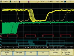
Figure 3 shows the type of metastable waveform detail that can only be captured with a high waveform update rate.
Figure 3. Infrequent Metastable States Captured Via Fast Waveform Update Rate
Courtesy of Agilent Technologies
Yokogawa�s Mr. Ting confirmed that serial bus triggering from logic channel inputs soon would be available in the DL9710L MSO. Although this MSO uses hardware serial bus decoding, the update rate is 15 waveforms/s as quoted in the DL9710L datasheet.
While on the subject of serial bus decoding/triggering, remember that you may not want to use certain digital channel capabilities even though they are available. For example, most MSOs can decode serial bus signals from a digital channel. But, digital channels present only a single-ended connection to the signal source. Some serial buses such as CAN require differential probing so you need to use a proper differential probe connected to an analog channel to directly probe the bus.
MSOs by Another Name
If you like the MSO functionality but perhaps need six analog channels and more than 16 or even 36 digital channels, why not create a custom MSO from modular instruments? For example, in addition to synchronized analog and digital input channels, a PXI-based system provides synchronized outputs to stimulate the DUT, very deep on-board memory, high data transfer rates via PXI Express, and virtually unlimited expansion
capability.
National Instruments� (NI) Scott Savage, product manager for high-speed digital I/O, explained some of PXI�s capabilities. “The PXI platform routes the same sample clock to all channels, ensuring analog and digital synchronization as close as 20 ps. Output signals share the same sub-nanosecond synchronization, and the system is scalable to suit your application.”
A typical NI system might include a PXI controller and multiples of the PXI-5152 dual-channel, 2-GS/s digitizer and the PXI-6552 100-MHz, 20-channel digital I/O module depending on the number of channels needed. Overall test system functionality is defined by a custom LabVIEW program. Of course, developing your own test program also means that you can directly address any special computation or report generation requirements not commonly found in traditional MSOs.
If your application includes several analog channels that need to be acquired with more resolution than an MSO�s 8 b, a system based on GaGe�s Octopus CompuScope might be appropriate. The Octopus is an eight-channel digitizer that samples input waveforms at up to a 125 MS/s rate with 12- or 14-b resolution. The board supports up to 4-GB of acquisition memory. This combination of numbers of analog channels, resolution, and memory length simply is not available in any MSO.
GaGe, like NI, can synchronize digital and analog channels. The CompuScope CS3200 Digital Input Card with 2 GB of memory provides up to a 100-MS/s sampling rate for up to 32 channels. Triggering across both digital and analog channels is supported but generally not at the same level as in an integrated MSO instrument. Nevertheless, very large on-board memories reduce the need for complex trigger conditions.
Conclusion
MSO competition has increased with the recent introduction of several models. This is good news not only because it gives you more choice as a consumer, but also because it confirms the usefulness of this class of instrument. Mixed-signal circuits and devices are here to stay, and it�s only natural that a type of instrument has been developed to solve the specific needs of mixed-signal design and development.
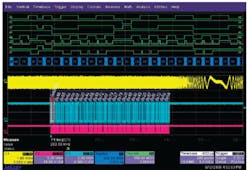
In general, DSOs and MSOs have become exceedingly versatile in the number and types of acquisition modes, trigger conditions, signal analysis features, and display capabilities such as the collapsed buses and separate PreVu and Zoom sections shown in Figure 4.
Figure 4. State, RS-232, and Parallel Bus Display, PreVu and Zoom
Courtesy of Tektronix
There are so many features in these products that a reasonable-size datasheet simply cannot do more than outline the available functions, even significant new ones. For example, MagniVu is an MSO feature that has migrated from the range of Tektronix logic analyzers. Similarly, Agilent�s FPGA dynamic probe feature originated as a logic analyzer capability.
To appreciate an instrument�s capabilities sufficiently, you need to use one for a week or two, examining the more challenging aspects of your mixed-signal application. Read the instrument datasheet a few times, but keep the manufacturer�s technical help phone number close at hand. You will need it, especially as you attempt to understand in detail the limitations of more complex triggering and acquisition modes.
And, if you still can�t find a suitable set of specifications, modular instruments may fill the need. You can count on new capabilities and combinations of features to appear with each generation of MSO products, extending the range of addressable applications. Nevertheless, a custom-designed modular instrument may be just what you require.
|
FOR MORE INFORMATION |
| Agilent Technologies | 6000 Series and Infiniium 8000 Series MSO | www.rsleads.com/707ee-178 |
| GaGe | Octopus CompuScope Board | www.rsleads.com/707ee-179 |
| National Instruments | PXI-5152 Digitizer | www.rsleads.com/707ee-180 |
| LeCroy | MS-500 MSO | www.rsleads.com/707ee-181 |
| Tektronix | MSO4000 Series MSO | www.rsleads.com/707ee-182 |
| Yokogawa Corp. of America | DL9710L MSO | www.rsleads.com/707ee-183 |
July 2007
