
When you�re relaxing with family and friends, do your conversations naturally turn to power supply efficiency? A few years ago, it�s almost certain that they didn�t. Today, they just might.
A number of high-profile initiatives within industry and at various government levels have highlighted the huge amount of power being wasted by inefficient power supplies. As a result, high efficiency has been added to the features-benefits marketing mix for consumer electronics products.
Several factors have contributed to the success of these initiatives. First, it technically is feasible to achieve greater than 90% efficiency even in relatively low-wattage power supplies. Experts agree that 95% is close to a theoretical limit. Second, the cost of the required technology is constantly reducing as the level of power IC integration
increases.
Third, whether from an ecological, economic, or personal convenience point of view, there are good reasons to buy products with efficient power supplies. For example, some new PC power supplies don�t need a fan. This means they are quiet, which is valued by users. And, media coverage of the relationship between climate change and power use has reached saturation level. You can�t help but know that wasted power is having a deleterious effect somewhere.
Nevertheless, the economic viewpoint is a hard sell. Consumer products require a low initial price regardless of long-term operational savings.
One way this problem has been overcome is through cooperation between power generators and PC manufacturers. The 80 PLUS� Initiative, administered by Ecos Consulting, is a forum uniting electric utilities, the computer industry, and consumers to bring energy efficient power supplies to desktop computers and servers. It encourages payments from the generators to manufacturers producing PCs with greater than 80% efficiency. This approach helped break the cost-volume deadlock by partially offsetting the higher cost of the new supplies until they became more prevalent.
Industrial power supplies are not as price-sensitive as those in commercial products. ATE power supplies have changed from a centralized to a distributed architecture with point-of-load regulation. Especially when high-dissipation devices and those with large and fast changes in power are considered, high current at low voltage can only be provided accurately with local regulation.
These systems typically consist of large bulk power supplies that provide raw DC to strategically located DC-DC converters. It is in these converters that manufacturers have used the latest technology to minimize losses. For example, Lambda�s PAH450S Series of single-output DC-DC converters has efficiencies above 90% for loads from less than 100 W to the rated full load of 450 W with a 48-V input (Figure 1).
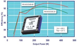
Courtesy of Lambda Americas
The TinyBuck� range of extremely compact integrated DC-DC converters from Fairchild Semiconductor measures 5 mm x 6 mm and achieves up to 95% efficiency. The devices come in a 25-pin, three-pad molded leadless package and convert inputs as high as 24 V into outputs as low as 0.8 V at up to 6 A. The Model FAN2106 6-A Regulator operates at frequencies between 300 kHz and 700 kHz. High switching rates allow small energy storage components to be used but increase demands on the switching devices.
Industrial applications value high efficiency because it saves space and reduces cooling requirements. Agilent Technologies provides the Model N6700 Modular Power System that can be configured as a one- to four-channel DC power system with up to 1,200-W output. Efficiency as high as 85% allows the system to be packaged in a 1-U high chassis. Conventional small fans supply the required cooling.
The Technology
Although it�s been possible to build high-efficiency power supplies for several years, recent developments have made it more practical. Even very small battery chargers for electric razors now use switch-mode technology rather than linear circuits. Linear supplies typically are limited to less than 50% efficiency.
Once a switch-mode approach has been decided upon, efficiency improvements can be made by reducing losses in a few key areas. Resonant topologies switch at zero current or voltage, and the switch itself can be improved. Today, most supplies use very low-loss MOSFETs rather than bipolar transistors with several types of enhanced-performance devices to choose among.
Controlling the switch or switches is another area of concern. Here, very detailed control timing and performance monitoring are accomplished by highly integrated controller ICs. These devices typically include an oscillator and timing logic, MOSFET drive circuitry, an error amplifier to accomplish regulation, a voltage reference, start-up circuits, and several types of protection circuits.
Because power supplies provide one or more DC outputs, losses due to rectification are receiving attention. Here, Schottky rectifiers often are used. Synchronous rectification can be more efficient than the best diodes, and magnetic amplifiers in some supplies achieve even lower losses.
Synchronous Rectifiers
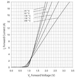
Schottky rectifiers are commonly utilized in applications requiring low forward voltage drop at high currents. For example, each of the two diodes comprising the common-cathode International Rectifier type 87CNQ020 can carry 40 A at 50% duty cycle and provides a 20-V reverse voltage. As is shown in Figure 2a, the forward voltage drop is highly dependent on the junction temperature, changing from 0.4 V at 20 A and 25�C to less than 0.25 V at 20 A and 150�C.
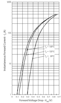
Courtesy of International Rectifier
In a 20-A supply, the diode losses would be between 2.5 W and 4 W, assuming 50% on time. If a synchronous rectifier MOSFET were used instead of the Schottky diode, its drain-to-source on resistance (RDS(on)) would need to be 20 m? or less. This follows from the MOSFET�s resistive loss P = I2 � R/2 = 4 W or 8/202 = 0.02 ? where the factor of two accounts for the 50% duty cycle. In fact, the International Rectifier type IRFBL3703 MOSFET is specified with a maximum 3.6-m? RDS(on), which would result in only a 0.72-W loss.
The decision to use synchronous rectification rather than a Schottky diode would be the correct one, but there are many more details to consider beyond the idealized improvement in efficiency. Schottky losses decrease with elevated temperature, but MOSFET RDS(on)-related losses become larger. RDS(on) increases by about 50% from 20�C to 110�C as shown in Figure 2b.
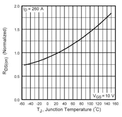
Courtesy of International Rectifier
In addition, extra circuitry is required to drive the synchronous rectifier where none is needed for the Schottky diode. The circuitry generates a gate drive with the proper timing. For the highest efficiency as well as improved reliability, there must be a small dead time between the series switch turning off and the synchronous rectifier turning on and vice versa.
You don�t want both devices on at the same time. More precisely, you don�t even want both devices turning on or off simultaneously. Changing from one state to the other takes time, and if the transitions of the two transistors overlap, current will flow through both, reducing efficiency.
In some cases, the synchronous rectifier MOSFET body diode maintains output inductor current during the on/off transitions. In other designs, a Schottky diode is used in parallel with the synchronous rectifier. An ON Semiconductor application note is available that evaluated HDTMOS transistors in a Buck regulator circuit.1
The soft reverse recovery of the body diode was one beneficial characteristic of the ON Semiconductor MTP75N05HD device tested. Because the softer diode recovered faster with a lower peak recovery current value than more conventional MOSFET body diodes, it could be used instead of a Schottky diode.
MOSFET type NTMFS4837NH is a new 75-A device with a 30-V rating rather than 50 V for the now-obsolete MTP75N05HD. The new transistor has a very similar forward diode characteristic but with less reverse recovery charge and a lower reverse recovery time. Finally, at 5 m?, the new device�s RDS(on) is half that of the older part measured under similar test conditions.
Also, as was discussed in detail in an International Rectifier paper presented at APEC 2004, some synchronous rectifier MOSFETs can turn on for a short time after they have been switched off. This is caused by the series switch turn-on transient coupling capacitively to the synchronous rectifier gate. This Cdv/dt induced switching loss affects some MOSFETs but not others. In the paper, the authors studied the behavior of two specially processed FETs, one that turned off cleanly and the other that did not.
Because there was a short time during which both the series switch and the synchronous rectifier MOSFETs were conducting, efficiency was reduced. To avoid this problem regardless of a MOSFET�s particular characteristics, the paper suggests a simple resistive divider to bias the synchronous rectifier gate, which has a capacitively coupled drive. The bias network serves to offset the drive waveform negatively, providing sufficient reverse bias to hold the MOSFET off regardless of transient coupling as the series switch turns on.
The paper�s detailed discussion of the Cdv/dt effect highlighted several MOSFET parameters as well as the importance of the MOSFET package: “For standard MOSFET packages such as SO8 and D-Pak, parasitic package inductance is the key component of the loop inductance. When silicon die with good Cdv/dt immunity is used in these packages, the Vds ringing caused by the inductance and the body diode reverse recovery current can easily exceed 30 V with a 12-V input voltage. High peak voltage as well as ringing can result in excessive EMI and reduce controller/driver reliability. It was shown that by replacing an SO8 package with a package with much lower inductance, such as a DirectFET�, the switch node voltage ringing can be reduced by as much as 50%.”2
Magnetic Amplifiers
In a switching regulator or switch-mode power supply, the output often is generated as a series of pulses or nominally a square wave. Full wave circuits use two rectifiers driven by antiphase outputs. Single-phase circuits may simply rectify the pulses and smooth the DC with a capacitor or LC filter. Alternatively, continuous output current can be provided by the combined action of a series switching device driving current into an inductor and a diode or synchronous rectifier that supports continuous current flow when the series switch turns off.
In any of these circuits, regulation must be accomplished by a separate means. If the supply or regulator produces only a single voltage, this is relatively straightforward. When multiple independent outputs are required, each must be separately regulated, adding cost and complexity and reducing efficiency. For this reason, the magnetic amplifier is a very low-loss control element utilized in high-efficiency power applications.
Magnetic cores with square B-H characteristics are used, which means that a small change in current can saturate the core. The core is wound with a main winding and sometimes a control winding. The main winding can have a high inductance that blocks current flow from the pulse output or, if the core is saturated, a very low inductance that allows the pulse current to flow. By changing the state of the magnetic amplifier core at the right time, the output pulse width can be controlled to achieve regulation.
It�s all about volt-seconds. If the control current causes magnetic flux to flow in the opposite direction to that caused by the output current, the core will be reset. The operating point will move away from the previously saturated region of the B-H curve to an area corresponding to high inductance. During the resetting action, energy measured in volt-seconds was added to the core. To transition back to the saturated condition requires the addition of that amount of energy in the opposite direction.
For example, if a net resetting voltage of -4 V is applied between nodes V3 and V4 in Figure 3 during the 10 �s that a 50-kHz squarewave output is negative, the core will be reset by 40 V-�s. The core will remain unsaturated until 40 V-�s has been provided by the next positive output pulse. If this has a 10-V amplitude, the leading edge of the pulse output from the magnetic amplifier will be delayed by 4 �s. The trailing edge will not be delayed.3
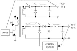
Courtesy of Texas Instruments
In practice, an integrated controller closes the loop around the magnetic amplifier and provides the necessary resetting signal to achieve regulation. The total power loss includes that of the control IC, the core loss, and the I2 R winding loss. This sum can be very small compared to the loss associated with a low-dropout linear regulator.
A recent Intersil application note detailed the use of saturable cores, also called saturable reactors, to improve the performance of a zero-voltage switching (ZVS) full-bridge. The magnetic amplifier terminology also describes a single-winding saturable core inductor but is better restricted to cores with both power and control windings.
ZVS is achieved by timing the switching to coincide with resonance of the transformer leakage inductance and the input MOSFET parasitic capacitances. It is common for ZVS to apply for only a relatively narrow range of loads.
Contrary to most designs that strive to reduce leakage inductance, ZVS works over a larger load range if the leakage inductance is higher. Two saturable cores are added to the secondary of the transformer and act to increase the effective leakage inductance. If the saturable core blocking inductance is high enough, the effective transformer inductance can be as high as its magnetizing inductance�much greater than the leakage inductance. According to the application note, ZVS can be maintained down to a 10% load using this technique.
Rather than include the saturable core in a magnetic amplifier feedback loop, these cores are used to change the transformer�s reflected impedance. Core reset is accomplished by the rectifying diode�s reverse current. This means that ensuring a robust design depends on a thorough characterization of core material and switching device performance. Nevertheless, because saturable cores have very low loss when saturated, the overall efficiency of a ZVS circuit can be increased by extending the load range for which ZVS conditions apply.4
Better Components
DC-DC regulation and switch-mode supplies are not the only efficiency-sensitive applications. Active power factor correction (PFC) circuits use similar components and have similar problems. However, because the PFC output is a high DC voltage, the optimum switching device characteristics are different.
Recently, Cree developed a range of silicon carbide (SiC) power diodes that works well in this application. SiC devices have several characteristics that set them apart from conventional silicon Schottky diodes. The most important of these are the very low stored charge and negative temperature coefficient of diode current.
Because the stored charge is very low, there is far less additional transient current to switch in the associated MOSFET than with a silicon diode. This means that the MOSFET runs cooler and possibly a smaller, lower-cost device can be used. Also, because the recovery is almost without ringing, EMI effects are reduced in addition to the need for circuitry such as snubbers.
Silicon Schottky diode current increases for a given voltage across the diode as temperature increases. SiC diode current decreases. This means that SiC diodes can be paralleled and the current will share. Finally, although the SiC diode forward voltage drop is >1 V where silicon Schottky diodes typically drop less than 0.5 V, in a high-voltage application this is not as important as the SiC diode�s other benefits (Figure 4).
Courtesy of Cree
To see the difference a SiC diode could make, Cree ran comparative tests in a 250-W PFC circuit. A 27% decrease in switching losses was measured as well as a reduction in MOSFET case temperature between 10 and 40�C.
Summary
Specifying or designing a power supply becomes very challenging when high efficiency is a prime requirement. The unpredictable loading a supply will encounter in an electronic test environment only adds to the difficulty.
Variable loading is a characteristic of many applications. To better represent a supply�s efficiency, a test method has been proposed to measure efficiency at 20%, 50%, and 100% of rated output. The three figures would be listed as well as the average efficiency.5
Maintaining high efficiency under light loading can be a problem. Agilent�s Peyman Safa, a hardware design engineer in the System Products Division, said, “Higher switching frequencies have put more pressure on efficiency levels at light power levels. Quasi- or full-resonant solutions, while addressing the issues of efficiency at these higher frequencies, have issues with control over wide operating points common in programmable supplies. Using our DSP-based control system allows us to improve efficiency while maintaining our level of stability and performance.”
Optimum control also is made difficult by the component parameter tolerance spread associated with commercial parts. ColdWatt manufactures high-efficiency power supplies for servers, and the company�s website discusses possible ways to overcome limitations caused by component tolerance:
“Normal component tolerances in analog circuits force compromises that [reduce] efficiency�. [Because] the optimal timing of the synchronous rectifiers is load dependent, adaptive and more accurate timing control can improve efficiency�. Digital controllers available today are capable of nanosecond-level timing control, virtually eliminating component tolerance sensitivities on the timing accuracy�. Digital controllers are capable of measuring internal operating parameters and using an algorithm to make complex and intelligent decisions, such as on-the-fly adjustments to improve efficiency.”
Even the power supplies that drive control circuitry within the power systems have come under scrutiny. Agilent�s Mr. Safa noted, “Extensive use of switching bias regulators, replacing linear regulators, has lowered internal losses. These losses are fixed and independent of output power so they represent a significant percentage of total losses at light load. Highly integrated switching regulators running at greater than 1 MHz have saved more than 9 W, they are very small, and the high-frequency switching noise is easily filtered.”
Obviously, commercial and industrial applications have different requirements. But, achieving the highest power supply efficiency depends on choosing the optimum architecture, switching devices, and integrated controllers. Volume applications contribute to the synergy in components and technology that benefits both types of products.
References
1. “HDTMOS Power MOSFETs Excel in Synchronous Rectifier Applications,” Application Note AN1520/D, ON Semiconductor, 2003.
2. Zhao, Q. and Stojcic, G., “Characterization of Cdv/dt Induced Power Loss in Synchronous Buck DC-DC Converters,” International Rectifier, 2004.
3. Mammano, B., “Magnetic Amplifier Control for Simple, Low-Cost, Secondary Regulation,” Texas Instruments, 2001.
4. “Techniques to Improve ZVS Full-Bridge Performance,” Application Note AN1246.0, Intersil, 2006.
5. Mansoor, Dr. A. et al, Proposed Test Protocol for Calculating the Energy Efficiency of Internal AC-DC Power Supplies, Revision 6.1, EPRI Solutions and Ecos Consulting, Sponsored by California Energy Commission Public Interest Energy Research (PIER) Program, 2006.
|
FOR MORE INFORMATION |
| Agilent Technologies | N6700 Modular Power System | www.rsleads.com/708ee-180 |
| ColdWatt | High Efficiency Server Power Supplies | www.rsleads.com/708ee-181 |
| Cree | Silicon Carbide Schottky Diodes | www.rsleads.com/708ee-182 |
| Fairchild Semiconductor | TinyBuck DC-DC Converters | www.rsleads.com/708ee-183 |
| International Rectifier | DirectFET Package | www.rsleads.com/708ee-184 |
| Intersil | ZVS Full-Bridge Integrated Controller | www.rsleads.com/708ee-185 |
| Lambda Americas | PAH300/350/450 DC-DC Converters | www.rsleads.com/708ee-186 |
| ON Semiconductor | NTMFS4837NH 75-A, 30-V MOSFET | www.rsleads.com/708ee-187 |
| Texas Instruments | MMagnetic Amplifier Controller | www.rsleads.com/708ee-188 |
| 80 PLUS Initiative | Energy Efficient Computer Power Supplies | www.rsleads.com/708ee-189 |
August 2007
About the Author
Comment About the Article
To join the conversation, and become an exclusive member of Electronic Design, create an account today!

Leaders relevant to this article: