Consumer demand for products that incorporate camera modules such as cell phones, automobiles, and even toys continues to grow rapidly. Sales of camera phones reached 295 million units worldwide in 2005 and will rise by 26% annually over the next four years according to Gartner Dataquest as reported in November 2005.
Mobile applications require small size and low power, yet consumers demand improved performance at an ever-decreasing cost. As a result, camera modules are becoming loaded with features such as zoom, auto-focusing, and auto-exposure capabilities. As an example, the manufacture of cameras for cell phones illustrates the principles that also apply to many other types of camera modules.
Optical Variations
As sensors become more densely packed, the assembly techniques required to align the lenses to them have become correspondingly more demanding. To achieve a sharp image over the full plane of the sensor and throughout the range of the zoom requires accurate alignment of the lens to the sensor in not just 1 degree of freedom (DOF), but in 5 DOF, to very tight tolerances. The tolerance typically is within 0.1� in pitch and roll and within a few microns in the focal axis of the lens.
Manufacturers have used machine vision for many years to compensate for variations in component parts in an assembly process. By using a camera and machine vision algorithms to align features (fiducials) on the critical parts of the components, the motion required for accurate assembly can be modified on the fly to compensate for variations in each part.
While machine vision is a great improvement over passive alignment, it still comes up short in aligning lenses. Why? Because machine vision can only align to fiducials on the surfaces of the components. It cannot take into account the optical characteristics of the assembly in operation, such as the focusing characteristics of the complete lens/sensor assembly.
The demand for embedded cameras in products has been enabled by innovations in lens and actuation technologies. These new technologies achieve high performance while minimizing size, weight, and power consumption, all vital constraints for mobile applications. However, these innovative products are difficult to manufacture and often lead to large optical characteristic variations within the same batch.
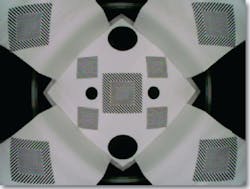
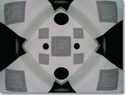
Figure 1a and Figure 1b show images from two lens assemblies taken from the same batch that look physically identical. They were aligned passively to the same position relative to the sensor, yet one appears out of focus.
Figure 1a. Target Image in Focus
Figure 1b. Target Image Out of Focus
Each lens assembly was aligned passively to the same sensor to the same position within 2 microns in the optical axis using the physical characteristics of the parts for alignment. Yet, they do not both result in equally sharp images.
From the outside features, these two lenses are equally aligned. However, because of the internal lens assembly variations or variations in the refractive properties of the lenses, the sharpness of focus for each lens is significantly different.
In this particular case, the variation in internal characteristics of the lens assembly has resulted in about a 100-micron variation in the focal length. No amount of external machine vision or passive alignment could have predicted or compensated for this optical variation.
Using Active Alignment
Active alignment is a technique for high-precision alignment of optical components. The component sensors and lens actuators are powered up and engaged for image analysis. Image alignment algorithms are applied to the actual image stream from the cell phone camera sensor during the assembly process.
3 DOF or 5 DOF Alignment?
Figures 1a and 1b showed how active alignment resulted in a compensation in Cartesian space to achieve sharp focus. But how important is rotational alignment, pitch, and roll?
Variations in the lens manufacture or in the movement of the zoom feature can easily result in a �2� misalignment in the optical axis. An additional source of error is the accurate placement of the sensor itself. This can easily account for an additional 2� or more of error.
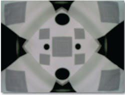
Figure 2 shows a camera alignment that has been optimized for overall focus in Cartesian space. However, look carefully at the image, especially at the corners. You will notice that parts of the image are very much out of focus. This lens/sensor assembly is misaligned by only 4�, yet it produces an image that is unacceptable for many applications.
Figure 2. Camera Assembly Optimized in Cartesian Space But With Rotational Misalignment
Zoom Lenses
Zoom lenses add to the complexity of optimizing the assembly for the sharpest focus. Zoom lenses can have different characteristics at different focal lengths. Exactly how they will perform at different focal lengths cannot be accurately predicted by looking at the outside of a lens assembly.
Simulation and analysis only approximate a particular lens assembly�s behavior. Focus at different areas of the camera, however, can be analyzed using active alignment at a series of focal lengths. Optimization algorithms also can compensate for misalignments along the zoom travel during assembly.
Particle Contamination and Defects
Camera sensors are very susceptible to particle contamination. While every effort is taken to assemble in a clean environment, dust and sensor pixel imperfections still are a significant cause of yield issues. A well-designed active alignment manufacturing process should identify image imperfections due to defective pixels above a predefined threshold, identifying imperfect sensors or lenses and particle contamination before assembly and increasing overall process yield.
What Makes a Good Image
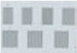
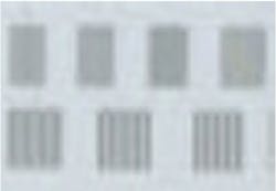
Deciding what types of alignment algorithms to apply is filled with pitfalls, too. Consider Figure 3a and Figure 3b. Generally, you would say that Figure 3a is crisper and in better focus than Figure 3b. Yet looking closer at the test card of each image, it would appear that fine features can be distinguished better in Figure 3b.
Figure 3b. Target Image�Fine Features
Applying modulation transfer function (MTF) analysis to both these images results in a higher score for Figure 3b. If the lens is intended to read bar codes, Figure 3b may be the better image for this purpose.
Computers, however, are not consumers, and most consumers would prefer the image in Figure 3a. Different analysis algorithms are designed for different purposes. Make sure you know what you are optimizing for and why you are using a particular set of mathematical tools.
Summary
The precision requirements for today�s camera modules necessitate the following:
� An active alignment process beyond the capabilities of simple machine vision.
� For most applications, alignment adjusted in 5 DOF, including pitch and roll, rather than in three linear axes.
� Alignment algorithm designed for a particular purpose.
� The need to choose the correct combination of algorithms for your purpose.
Sophisticated Active Alignment Automation
Active alignment manufacturing systems, such as Automation Engineering�s CMAT Camera Module Assembly Station, enable successful high-performance products using innovative, lens/sensor assemblies requiring very high precision alignment. Last year, about 370 million camera phones were sold worldwide. The difference between a successful, innovative product and a me-too product can be around 5 million units per year.
Innovative products can add a staggering $1 billion to a company�s sales. Benefits are not limited to the fruits of producing high-performance products. On the other end of the equation, an increase in throughput and an increase in yield of 10% can result in cost savings of millions of dollars a year for camera phone manufacturers, savings that flow directly to the bottom line.
About the Author
Justin Roe is COO at Automated Engineering and a Chartered Engineer. Before joining the company, he was a management consultant for Integral and a general manager of Wodson Engineering in England. Mr. Roe received a B.S. from the University of Edinburgh and an M.B.A. from Harvard Business School. Automation Engineering, 299 Ballardvale St., Wilmington, MA 01887, 978-658-1000, e-mail: [email protected]
FOR MORE INFORMATION
on camera module assembly
and test systems
www.rsleads.com/709ee-185
September 2007
