Connectors are a Major EMI Weakness
What You'll Learn
- How to mitigate EMI when it comes to cable and connector selection
- What types of filters can be employed to address EMI and connector system design
A large majority of EMI problems, including both emissions and immunity, involve interference currents conducted into and out of the box via a power or data cable. These currents can be controlled by filtering or shielding, often through a connector.
Detailed design guidance for connector and filter design and selection would fill a book. But many problems can be avoided by taking some basic steps including proper mounting of the connectors to the cable and bulkhead, filter selection, and choice of the connector type.
Design Decisions
Some basic design decisions need to be made before the connector type can be selected.
- Is the enclosure going to be shielded? Low-cost consumer electronics avoid use of a shielded enclosure. Depending on the performance requirements of the electronics, this may be a difficult task requiring very careful circuit board design and appropriate filtering of I/O.
- If the enclosure is to be shielded, will the cable also be shielded? If not shielded, then filters and transient protection may need to be incorporated into the design.
- What is the environment? Are we talking about a fairly benign commercial requirement or a rough military environment? Military environments may have severe EMI and transient requirements.
Unshielded Enclosures
For unshielded enclosures, it doesn’t make much sense to use shielded cables, leaving filters as the only option. The connector is simply an interconnect between circuits on the board and wires in the cable.
While filtering can be incorporated into the connector, it usually can be achieved less expensively on the circuit board. Then the connector is only a connection to the wires leading to the outside world. As a result, connector selection is not important, generally needing to be compliant only to an industry standard or one already in use by the manufacturer.
The key is the physical placement of the filter elements and the connector to minimize field coupling between key circuit board elements and the connector. Common-mode currents are a major emission problem in unshielded electronics and cannot be handled with capacitive filters commercially available for interfaces like Ethernet. Instead, common-mode chokes are advised.
Shielded Enclosures
With a shielded enclosure, the choice is whether to use a shielded cable, a filter, or rarely both. Shielded cables are better for EMI than filtered lines and may be mandatory for high-speed signals that cannot tolerate filtering. But filtering may be acceptable for low-frequency signal lines. Filtering for power input is pretty much unrestricted, and shielding power cables often is not feasible.
Shielded Enclosure, Shielded Cable
The shielded enclosure-shielded cable situation is almost automatic for military environments but increasingly common in commercial applications as well. Military-style connectors are designed to facilitate EMI control, as are some but not all commercial-style connectors. The key to successful application of shielded cables and connectors is in the mounting.
There are several basic requirements for successful cable shielding, all ensuring full conductive continuity between the cable shield and the bulkhead. Basically, this means that:
- The cable shield needs to mate fully with the cable connector.
- The cable backshell halves need to mate with each other.
- The cable connector needs to mate fully with the bulkhead connector.
- The bulkhead connector needs to mate with the bulkhead
All of these surfaces must mate continuously, or the shielding performance will be degraded.
The most common error is in mating the cable shield to the connector shell. To be fully effective, the connector shell needs to mate around the cable shield. Pigtail connections are not acceptable. And running the cable shield drain wire through a connector pin turns the cable shield into a dandy antenna with a matching network.
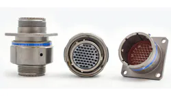
The situation is reasonably well handled with MIL-DTL-38999 series connectors (Fig. 1) designed to facilitate shield terminations as well as accommodate filters and transient protection. The cable shield passes through a compression ring, permitting a circumferential connection.
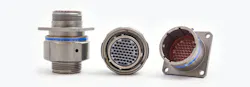
Individually shielded cables such as a shielded twisted pair can be mounted in groups, with each individual shield being tied off to the compression ring. This is a common need in military/vehicle/aircraft cables where complex wire harnesses are the rule.
The shield terminations need to be made with care. The overall shield must be terminated circumferentially with provision to firmly press the mating surfaces together. Where individually shielded wires are brought together into a single connector as is common in aircraft and other vehicles, the individual shields cannot be terminated circumferentially to the compression ring.
The best that can be done is to keep the pigtail to an absolute minimum such as 1 mm with the termination to the ring being placed immediately adjacent to the cable shield. Contract cable assembly houses are notorious for using 1-inch pigtails or not terminating the shield at all.
The problem is worse with commercial connectors where it may be difficult to achieve a satisfactory cable shield termination and is unmanageable where foil cable is used. The problem is in attempting to get a circumferential connection between the conductive side of the metallized foil and the connector shell.
It is nearly impossible to effect such a connection in a workmanlike manner, and even if successful, the connection still is structurally unsound. More often, a compromise solution is used, such as running the drain wire to a screwpost inside the backshell. This is likely the termination method if you buy a commercially assembled shielded cable. It leads to a mediocre shield inadequate for demanding applications.
The mating surfaces in commercial connectors and receptacles should be considered as well. Some connector manufacturers encourage a tight fit by putting dimples in the mating surfaces, and this has been effective in many cases.
Finally, there is the fastener and connector cutout at the bulkhead. Military-style connectors use a jam nut or a screw mount in all four corners, making it easy to get good mating contact and potentially avoiding the need for gasketing.
In the commercial world, connectors generally are poorly designed, having only two screws at the long ends of the connector. This practically ensures poor conductive contact on the sides, especially if the cutout is too big. Minimize cutout size and put in some gasketing. Die-cut gaskets work fine in such applications, and a single gasket can accommodate multiple connectors.
Effective RF shielding requires that the shield at both ends of the cable be grounded to the shell. Single-point grounding is very effective for audio frequencies such as 50/60 Hz but unacceptable for high-frequency shielding. Be aware that cables bought from a local computer supply store usually are ineffective. In most cases, the cable shield is grounded at one end, has pigtail terminations, or both.
Shielded Enclosure, Cable Unshielded
For unshielded cables, filters and transient protection will be needed. Filters and transient protectors may be mounted in the connector, on the circuit board, or a combination of both approaches, provided certain mandatory conditions are met.
As with shielded cables, connector grounding to the enclosure is absolutely imperative for the filter to work effectively. Most filters will involve a capacitor shunted to the enclosure boundary, and most transient protectors similarly will need to be shunt-mounted to the enclosure.
Filter Basics
There are two ways to filter: either block interference currents by inserting a high-impedance series element or divert currents by inserting a low-impedance shunt device. Basic filter theory says that maximum filter effectiveness occurs with maximum impedance mismatch at each node.
A low-impedance shunt element should face a high-impedance source or load, and a high-impedance series element should face a low-impedance load or source. This is shown in the matrix where the filter combinations of both low and high impedances for input and output are depicted. Here, high and low are relative to adjacent circuit elements.
Filter Combinations for High/Low I/O Impedance
Each line in the connector usually is filtered. This amounts to a lot of lines in, for example, a 120-pin connector.
Shunt Filter—Capacitor
The most common filter element in connectors is a simple shunt capacitor per line. When installed in a connector, capacitor filters rely on the assumption that the capacitor impedance is low compared with the source or load impedance. If the primary concern is emissions, the impedance of the capacitor should be low compared with the source impedance inside the housing. This probably is a fair assumption for input circuits but not for low-impedance drivers.
If the primary concern is susceptibility, the assumption is that the line impedance is high, but this is not always the case. The filter capacitor may well resonate with the cable reactance at some frequency, degrading the performance. Problematically, this will depend on the cable at each installation so performance is unpredictable. Nevertheless, the capacitor filter is the first choice and often adequate for the job.
The capacitors must be rated to handle the expected worst case, which usually is an external transient.
The least expensive capacitive filters are those made of chip caps mounted on a wafer with holes for the connector pins. These even are available in flexible wafers that can be installed in an existing connector. For quick fixes, another alternative is plug-in filter connectors; just pull the connector, install the insert, and replug the connector.
For better high-frequency performance, tubular feedthrough type capacitors are used, especially in demanding military designs. These devices have lower inductance and consequently higher frequency performance.
Filter connectors are available in common connector types in various capacitor values, and custom designs permit a mix of capacitor values.
Series Filter
Much less common is a series impedance element. When installed in a connector, the basic assumption is that the series impedance is high compared with the source and load impedance.
In principal, series filter elements can be a wound inductor, a ferrite inductor, or a resistor. But ferrites are best for use in connectors. That’s because they provide modestly high impedances at frequencies greater than 1 GHz, becoming lossy enough to minimize resonance problems. They commonly are formed around a wire or connector pin to insert the series impedance and often are used with capacitors.
Ferrites are particularly useful for blocking common-mode currents in unshielded enclosures. Common-mode chokes are particularly effective for this problem. However, they are more readily mounted on the circuit board because they don’t mount well inside a connector shell. In RG-45 connectors, ferrites are available in a single block with holes cut for the signal pins.
Ferrites need to be rated to handle the expected current, whether transient or steady state, as with power input. Ferrites have high permeability and will start to saturate at even modest currents.
Wound inductors are too bulky to be used effectively in a connector and generally are only suitable for low frequencies. Resistors also are possible but only in signal cases where the DC drop can be tolerated, as might be the case with low-frequency, high-impedance sensors. Wound inductor and resistor filter elements typically are installed within the enclosure, not in the connector.
LC Filter
A combination of a series inductor, usually a ferrite, and a shunt capacitor makes up an LC filter. If the ferrite faces the cable, it is well suited to handle external interference. It limits the amount of current entering the enclosure, especially during resonant conditions on the cable. If the ferrite faces the internal circuits, it is well suited to minimize emissions from low-impedance drivers.
Ω Filter
The Ω filter, like the C filter, is best suited to high input impedance and high output impedance with the additional blocking capacity of the series element. Unfortunately, specified attenuation never is achieved in practice.
Filters usually are tested with 50-Ω input and output impedances, neither of which is realistic in actual applications. The attenuation can be expected to be 20 dB lower than advertised or even worse. Again, it is absolutely imperative that the connector ground to the chassis ground connection be near perfect; otherwise, the filter performance will suffer significant degradation.
T Filter
The T filter is best suited to low input and low output impedances and has the advantage of dampening resonant conditions at both cable side and internals. Unfortunately, the T filter requires two ferrite filter elements, an approach not really well-suited for connector applications. However, these are good choices for use in unshielded enclosures. If T filters are to be used, they usually are mounted on the circuit board in unshielded enclosures or in the form of supplementary filter elements inside a shielded enclosure, immediately adjacent to the connector.
Composite Filters
Clearly, other filter elements can provide additional filtering. Generally, these are mounted inside the enclosure in a doghouse, a small metal box mounted immediately inside the housing at the connector. This is a very common practice for demanding military applications where a wide frequency range is to be filtered or where transient suppression is to be incorporated.
Transient Suppression Elements
If the primary threat is external transients, transient suppression elements may be used in place of capacitors or in parallel with capacitors. The two most popular devices are the metal oxide varistor (MOV) and the silicon avalanche device (SAD). The MOV is more robust and can better tolerate overloads. However, because it doesn’t have as sharp a breakdown, an MOV is more commonly used for power; the SAD is more widely used for signal lines.
Summary
Many EMI problems, whether related to emissions or immunity/susceptibility, are cable related and that usually boils down to the treatment of the cable connectors. These problems can be mostly avoided by taking some basic steps. Bolt the connector down tight, circumferentially terminate the cable shield, and match the filter elements to the threat.
About the Authors
William D. Kimmel, PE, and Daryl D. Gerke, PE, are partners in the EMC consulting firm of Kimmel Gerke Associates.
Original publish date: October 2009
About the Author
Comment About the Article
To join the conversation, and become an exclusive member of Electronic Design, create an account today!

Leaders relevant to this article: