Test Challenges of Wi-Fi and Bluetooth Devices

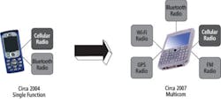
The mobile phone market is undergoing its next phase with the transition from largely single-connectivity cellular-only phones to multistandard connectivity or cellular + Bluetooth + Wi-Fi phones (Figure 1). The increasingly ubiquitous smartphone embodies this development.
Multicom devices are a key enabler in this transition, allowing the demanding form factor and power-consumption metrics to be achieved for the mobile handset market. According to ABI research, one-third of all multistandard solutions will be enabled with multicom devices by the year 2012.
Prior to the development of multicom devices, mobile phones were built using single-function radio devices. Typically, it required only one or two of these to provide cellular and Bluetooth capabilities.
With the advent of multiple connectivity radios, the proliferation of different radios dictates a new design methodology, giving birth to multicom devices. The obvious implications include fewer components and less board area.
Test implications often are less obvious but perhaps more profound: multiple wireless test technologies in one test station, increased port connections, more complex test software, and concurrent testing. Traditional standard-per-tester architectures no longer are optimal for testing multicom devices, either technically or economically.
Bluetooth and Wi-Fi Proximity Challenges
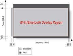
Bluetooth and Wi-Fi operate in the same frequency spectrum. Bluetooth uses 79 channels that span 2,402 MHz to 2,480 MHz. Transmit power levels achieve +4 dBm for class 2 devices, the most common in mobile electronics, while receive sensitivity ranges to -90 dBm.
Wi-Fi devices support transmit-power levels from +15 dBm to +20 dBm for 802.11g and 802.11b, respectively. Sensitivity ranges to -95 dBm depending on the implementation.
Wi-Fi and Bluetooth devices sit squarely atop one another as shown in Figure 2. Most multicom devices use sophisticated algorithms to ensure that Bluetooth and Wi-Fi data is time-multiplexed so that the two standards do not interfere with each other. This is particularly critical when receiving data on one standard and trying to transmit data on the other.
What does this imply for test? In design verification, these coexistence algorithms are likely to be verified, but that should not be required in manufacturing test. However, that does not mean that the test implications are trivial. To understand this more fully, we need to review some basic architectural aspects of the software and hardware in these devices.
Architectures and Test Implications
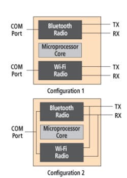
The typical multicom device usually will contain two or more independent radio architectures depending on the number of standards served. The RF connections for these radios typically are brought into or out of the device either independently or shared. Figure 3 shows two examples of this approach.
The topologies illustrate just two of the potential RF port arrangements that might be used on a multicom DUT. Test equipment port configurations need to be flexible to deal with these various topologies.
A solution with ports focused on a particular standard could easily lack the flexibility required to interface efficiently to these devices. Conversely, a solution with port assignments that cover every possible standard will likely add unnecessary costs. It also could compromise performance due to the difficulty of optimizing numerous RF parameters for a broadband impedance match needed as even more radios are added.
A microprocessor/microcontroller core makes up the next significant architectural component of multicom devices. These cores typically require some kind of firmware to be loaded to the device at test time to enable functionality and support calibration processes. Should there be one firmware file containing all needed standards or multiple files? Should there be one communications (COM) port or multiple ports?
If the firmware is broken into multiple blocks, such as Wi-Fi and Bluetooth, then both can be loaded into the DUT in parallel over two COM ports as shown in Configuration 1. If there is only one firmware block, then it will have to be larger to include both Bluetooth and Wi-Fi capabilities. As a result, loading time will be longer over one COM port. This can have a large impact on test time since firmware loading and boot time can account for 15% to 20% of the total test time for a DUT.
Test software should be architected well before a device ever tapes out to ensure the best possible test performance. That, in turn, will equate to tangible manufacturing cost reductions over the life of the device. Figure 4 illustrates two possible test software architectures for a multicom device.

Multicom devices are most frequently put into mobile phones where an application processor runs the core device and peripheral functions. Consequently, the application processor serves as a gatekeeper to the multicom DUT. All communications to and from the DUT must go through this layer.
In a multithreaded approach, the external test software can communicate to the various radios in parallel; single-threaded applications require serial communications. Again, this has key implications on test time because a multithreaded implementation can be tested much quicker regardless of the test equipment’s capability.
Tester Architecture Implications
Concurrent test is the first test equipment challenge. It allows multiple device functions to be tested in parallel, dramatically shortening test time over serial and multi-insertion methodologies. But, how can standards that overlap in frequency like Bluetooth and Wi-Fi be tested in parallel?
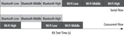
Typical tests include the low, middle, and high frequency portions of the band. For a two-technology multicom device, this equates to six key test sequences for transmit (TX) and six sequences for receive (RX).
As shown in Figure 5, the receive portions of the combined Bluetooth and Wi-Fi tests have been cut by one-third in test time by performing the high and low portions of the band concurrently. This strategy requires support from the DUT software driver. Again, this points to the need of test engineering to be closely involved with the device design team for both hardware and software.
As shown in Figure 2, a Bluetooth signal is generated in the low end of the band at 2,402 MHz, and a Wi-Fi signal originates in the upper end of the band. Assuming the test equipment has sufficient baseband signal-generation bandwidth, you can apply this measurement approach. This also requires appropriate waveform-development software from the instrument provider to generate these multistandard waveforms.
Test Flow Implications on Overall Throughput
Traditionally, we test multicom devices using multiple test stations or test lines, each focused on a particular technology. This often is common as companies with test equipment for one standard add test equipment for new standards as required. At first glance, this would seem to minimize capital expenditures and offer the capability to choose best-in-class equipment for the particular standard desired. Upon closer examination, this often is not true when the total costs are considered.
Handling time becomes more significant as standards are added. If physically separate test stations are used, a handling step is required for each device technology. In a device with two or more standards, this has the effect of increasing handling time from about 8% to 16% or more of the total test process time.
Additionally, the multiple station approach results in work in process (WiP) due to batches of material moving from test station to test station. This further reduces manufacturing efficiencies and adds cost.
The next evolution in test processes is to move to test stations that enable all of the device functions to be tested in a single connection. This delivers a 16% test time reduction and eliminates WiP, improving factory efficiencies. Finally, as there is only one handling step, it decreases the chance for errors along with the possibility of damaging the DUT through mishandling.
In the ultimate evolution, test time can be reduced by more than 50% from the serial-flow, dedicated station.
This is accomplished through key methodologies:
• Utilizing test equipment with concurrent test capabilities such as testing Wi-Fi and Bluetooth low and high bands in staggered fashion.
• Enabling concurrent test software functionality in the DUT driver and application processor so Bluetooth and Wi-Fi functions can run in parallel.
• Utilizing multiple independent DUT drivers per technology to enable parallel loading/boot-up.
Successfully implementing all these key facets requires close cooperation between the device manufacturer and test equipment vendor. Even within the device manufacturer’s team, synergy between the design team and the test team is needed well before the device ever reaches tape out.
Certainly, these advanced test methods can complicate the test development process due to the number of different groups and companies involved. However, by performing this work up front, the operational savings will pay dividends as these devices reach very high volumes.
Summary
As multicom devices proliferate, test equipment and methodologies must keep pace for costs to be kept down. Test strategies for these devices must include device hardware and software engineering teams, test equipment selection, and test-flow choices. None of these areas can be dealt with in isolation.
About the Author
John Lukez is director of product management at LitePoint. His experience includes R&D measurement and characterization, semiconductor high-volume manufacturing test, and system-level characterization. Mr. Lukez holds a degree in electrical and computer engineering from Ohio State University. LitePoint, 575 Maude Court, Sunnyvale, CA 94085, 408-456-5000, e-mail: [email protected]
March 2010
About the Author
Comment About the Article
To join the conversation, and become an exclusive member of Electronic Design, create an account today!

Leaders relevant to this article: