Evaluating 4G Performance With New MIMO OTA Test
Emerging 4G mobile wireless radio technologies such as long term evolution (LTE) and WiMAX are focused on delivering higher levels of throughput. Multiple input, multiple output (MIMO) operation is the foundation for these technologies to enhance the overall performance of radio transmitters and receivers with respect to the effects of the air interface. MIMO systems use multiple transmit and receive data paths to provide significant increases in data throughput by exploiting the characteristics of the radio channel. Accordingly, MIMO system performance is directly related to the propagation environment in which the device is operating.
Some testing, which is functionality focused, is performed using conducted testing. With conducted testing, the radio transmitters and radio receivers are directly connected using RF cables and connectors, offering controlled and repeatable testing but lacking real-world dynamic conditions that are introduced when signals are transmitted over the air (OTA). Conducted testing can be greatly enhanced using channel emulation, where channel emulators use propagation models to recreate the dynamic OTA conditions typical in mobile wireless conditions.
While this test method provides significantly useful information about performance, any conducted testing removes the antenna from the test equation. OTA lab testing is the best method for controlled, repeatable full-system test.
OTA testing is critical to performance testing of MIMO transmissions, and a number of MIMO OTA test solutions are being proposed in the wireless industry. These solutions must be capable of providing a comparable and efficient platform for testing devices to allow effective benchmarking and ultimately allow the tester to deliver an accurate good/bad prediction of performance without leaving the controlled conditions of the lab.
A new solution for MIMO OTA testing combines a channel emulator with a reverberation chamber to create a shielded environment for testing EMC and other EM investigations that achieves MIMO throughput performance testing and enables accurate good/bad wireless MIMO device performance prediction.
Testing for MIMO Performance
Performance of devices that use MIMO technology is dependent on many factors, but it is highly influenced by the propagation environment in which the device operates. Operational environments of the device, such as indoor, outdoor, rural, urban, nomadic, mobile, or highly mobile, become a basic set for which the device must be tested. Testing using a conducted methodology often is performed using an emulated RF channel via a MIMO channel emulator to recreate the complex propagation conditions typically seen by a device.
The requirements of these RF propagation conditions, or channel models, have been established, and a set of industry-standard channel models has been produced, such as specified in 3GPP TS 36.521-1.1 Although these models statistically represent the conditions as found in real life, they do not represent any specific condition. Nonetheless, these models have been accepted and endorsed by the industry as the sufficient requirements for testing performance of the device in a conducted fashion.
The existing set of industry models provides a strong, well-understood, and already adopted basis for these conditions and can be easily adapted for OTA testing. The standard channel models as defined for MIMO testing largely comprise three major channel phenomena:
• Multipath, specified by a power delay profile (PDP).
• Fading, specified by a Doppler spectrum.
• Spatial and directional effects as specified by MIMO fading correlation.
These characteristics will allow a similar set of propagation conditions to be defined for testing a device using an OTA methodology.
Testing the overall device as it would normally operate is simply the best way to understand the performance as experienced by the user. This means testing the entire device in an active operational state.
It is important to test the device with the actual interaction of the antennas, RF front ends, and baseband processing elements. It also is useful to test the device with a performance metric or Figure of Merit (FOM) consistent with user operation and experience to provide a real-world metric.
As MIMO devices are defined to provide enhanced throughput, data throughput becomes a very real FOM. Industry groups such as 3GPP, RAN4, and COST2100 have recommended that data throughput is the preferred FOM for MIMO OTA testing. Other tests such as total isotropic sensitivity (TIS) and total radiated power (TRP) also are being considered as FOMs to evaluate a MIMO device.
Proposed MIMO OTA Methods
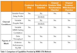
Several candidates for MIMO OTA methods have emerged from the work of 3GPP, RAN4, and COST2100. Although there may be variants of each, the main solutions are summarized in Table 1 along with a comparison of conducted emulator-only testing.

A channel emulator and reverberation chamber combination solution can provide the modeling flexibility needed to accurately test the performance of devices that use MIMO technology. Other solutions, such as larger anechoic chamber-based systems that also use channel emulators, can supply the necessary propagation conditions as well. When choosing an OTA test system, additional factors for consideration and comparison include acquisition and ownership cost, ease of use and calibration, and portability.
Combined Emulator/Chamber
A channel emulator cascaded with a reverberation chamber gives many degrees of freedom for creating specific channel conditions and producing FOM useful in MIMO OTA test. It has already been discussed how a reverberation chamber alone can be used for a FOM of TIS and TRP measurements through the work of CTIA. Now the focus shifts to MIMO channel conditions and data throughput FOM. The channel conditions include multipath or PDP, Doppler spectrum, and MIMO correlation.
Power Delay Profile
The scattering of EM waves within a reverberation chamber creates a Rayleigh distributed signal amplitude at a receiver. The reverberation can be damped or loaded to create a PDP or multipath delay with various decay times using, for example, blocks of RF absorber material, a phantom head, or a tank filled with liquid.
This use of a reverberation chamber alone creates a dense exponentially decaying PDP with an rms delay spread that is a function of the chamber loading.2 Although this may be appropriate for a single cluster model, it is not representative of the typical multicluster or outdoor urban models. Standard channel models as defined by 3GPP for LTE testing1 typically have many discrete multipath environments with greatly delayed multipath components. Using the channel emulator and reverberation chamber solution, PDPs to support both indoor and outdoor environments can be accurately created.
A DUT is placed in the reverberation chamber and exposed to the multipath components arriving from many, generally uncontrolled, angles of incidence. When the device response is averaged over all paddle positions, a so-called uniform spatial channel is created. The uniform channel provides a useful model for many applications and creates an overall 3-D isotropic environment. As most MIMO devices are intended to operate in all orientations and not just an azimuth plane, this environment is very helpful in understanding real-world performance.
A channel emulator is placed in the signal path of the reverberation chamber to produce a cascaded response. The channel emulator can be configured with multiple taps with fixed weights ?k and excess delays ?k to create a specific impulse response:
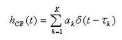
This is referred to as a static channel emulator impulse response because of the fixed tap weights. Using the channel emulator provides additional discrete delay impulses placed at whatever excess delay is required. The resulting overall response is the convolution of the emulator impulse response with that of the chamber.
Using this technique, a desired PDP can be created. An example of such is shown in Figure 1. The system is driven with an arbitrary but representative PDP as indicated in the lower part of the figure, and the resultant multipath is measured at the DUT location for a variety of chamber loadings. Accordingly, PDPs as given by standard indoor and outdoor channel models can be created.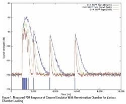
Doppler Spectrum
The PDP was referred to as static but actually was time-varying according to the motion within the chamber. The chamber motion is given by the paddle or stirrer movement but is relatively slow, creating a Doppler shift that is on the order of a few Hertz. For a mobile device, this may not adequately represent the range of motion it will encounter in typical operation.
To model higher Doppler shifts, independent Rayleigh fading is introduced on each emulator tap. The channel emulator’s impulse response then is described as
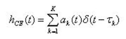
A classical Jakes spectrum can be programmed, as it is commonly used in mobile radio, or the TGn Bell spectrum.3
When the channel emulator and reverberation chamber are cascaded, the fading produced by each is multiplied in the time domain, so the overall Doppler spectrum becomes the convolution of the Doppler spectra of each part.
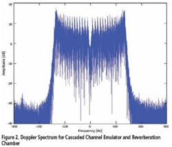
The results show that Doppler, or device velocity, can be created with the proper Doppler spectrum as given by standard channel models with the channel emulator and reverberation chamber combination.
MIMO Fading Correlation
MIMO correlated fading can be provided by proper programming of the channel emulator. A specific correlation matrix is programmed into the channel emulator for the desired correlation at the DUT. The correlation matrix used takes the form of a Kronecker product:
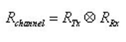
The correlation on the user equipment (UE) side of the link is determined by the properties of the UE antenna array itself and not programmed into the emulator. The correlation can be defined on a tap-by-tap basis, as is the case with standard MIMO channel models.
Fading correlation of the combined channel emulator and reverberation chamber is measured using a test setup with two receiving antennas in place of an actual device. After selecting the correlation to be used by the emulator, the emulator and reverberation chamber are started (fading and stirrer motion).
The system is paused after a few seconds, during which a measurement is made of the system response with the vector network analyzer (VNA). The VNA collects samples over a 40-MHz bandwidth on both receiving antennas. Fading and stirrer motion is resumed, pausing again after a few seconds, and another measurement of the system response is made. This is repeated many times. Post-processing this data yields a measurement of the fading correlation between the antenna paths.
The correlation measurements were performed over a range of transmitting probe or wall antenna spacings to determine the impact this also may have on correlation. The results, shown in Figure 3, illustrate a very strong dependence on the desired or set emulator correlation and virtually no dependence on the spacing of the wall antennas. Note that Ant 3 and 4 in the figure are those of the receive antennas at the DUT location.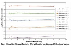
For these tests, all correlations were real-valued. The results illustrate that the MIMO correlation matrices defined in Reference 1 are supported by this technique, at least on the eNodeB side of the link. The results show that correlation, as given by standard channel models, can be created with this solution.
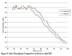
Good vs. Bad Device
The aspects of a good vs. a bad device using a MIMO OTA test method can come in many forms, but for this example, a good vs. bad antenna design was evaluated. In this experiment, two of the same 802.11n MIMO devices were procured, and on one sample, the antennas were altered to create a bad antenna design. Both devices were evaluated in the OTA test method described with the FOM being throughput. As Figure 4 illustrates, with only a change in antenna, the bad device performed worse than the good device as observed by the MIMO OTA test system using the FOM of data throughput.
Conclusion
The channel emulator and reverberation chamber system MIMO OTA methodology shows that it is possible to emulate standard channel models used for cabled testing in a relatively small and portable OTA environment as an alternative to using a large anechoic chamber. The combined channel emulator and reverberation chamber system enables flexibility in creating static or dynamic PDPs, use of much higher Doppler rates, and programmable downlink fading correlation. It provides a simple, true OTA modeling framework with enhanced realism over the use of the reverberation chamber alone and can offer a practical solution for enhanced MIMO OTA testing.
References
1. TS 36.521, v8.4.0, User Equipment (UE) Conformance Specification Radio Transmission and Reception Part 1: Conformance Testing.
2. Chen, X., Kildal, P-S., Orlenius, C., and Carlsson, J., “Channel Sounding of Loaded Reverberation Chamber for Over-the-Air Testing of Wireless Devices–Coherence Bandwidth Versus Average Mode Bandwidth and Delay Spread,” IEEE Antennas and Wireless Propagation Letters, Vol. 8, 2009.
3. Erceg, V., et al, “TGn Channel Models,” IEEE P802.11-03/940r4, 10 May 2004.
About the Author
John Griesing is vice president of R&D at Azimuth Systems. Prior to joining Azimuth, he was a senior director at 3Com and general manager of engineering for Chipcom’s David Systems division and held design positions at Chipcom, Wang Labs, and RCA. Mr. Griesing has an M.S. in electrical engineering/data communications from Northeastern University and a B.S. in electrical engineering from the University of Connecticut. Azimuth Systems, 35 Nagog Park, Acton, MA 01720, 978-263-6610, e-mail: [email protected]
About the Author
Comment About the Article
To join the conversation, and become an exclusive member of Electronic Design, create an account today!

Leaders relevant to this article: