A Union of Embedded Test Expertise

Taken literally, embedded test is just that: test capabilities that exist wholly embedded within a system. Power-on self-test is an example as is a built-in performance-monitoring feature programmed to do something if an exception occurs. Many microprocessors and microcontrollers either include or work with a watchdog timer that performs a system reset if the watchdog times out. Depending on the nature of the overall application, several performance-related metrics could be periodically checked before each reinitialization of the timer.
More broadly, embedded test refers to testing embedded systems. This definition includes external access for debugging purposes as well as to receive data from and send control commands to on-board test resources. It’s important to distinguish between access mechanisms such as the IEEE 1149.1 test access port (TAP) and the actual testing facilities that exist within the system. Today’s terminology calls these resources instruments and includes all kinds of design-for-test (DFT) capabilities such as built-in self-test (BIST) and scan.
1149.1
The quest for comprehensive test coverage dates at least from the late ‘80s when PCB test points began to disappear. BGA packages, SMT components, multilayer PCBs, and sensitive high-frequency data I/O connections all contributed to less and less test access. No longer could high fault coverage be achieved through in-circuit test based on physical contact.
The industry’s answer was IEEE 1149.1 Boundary Scan, also called JTAG after the Joint Test Action Group that later became an IEEE working group. This solution remains well respected, proliferating beyond its original use for checking solder-joint integrity to provide a widely adopted access mechanism. Several related 1149.x standards have been issued over the years to address new test challenges, but the underlying parallel-load, serial-shift operation remains a fundamental concept.
It’s interesting to read some of the early documents written when 1149.1 had just been finalized. Kenneth Parker’s The Boundary-Scan Handbook 1992 edition is a good example. In a chapter on advanced boundary scan testing, Dr. Parker proposed that it should be possible to completely automate many DC parametric tests. Also, using the sample instruction should support implementation of a logic analyzer function through the 1149.1 port.1
Some test capabilities became more popular than others, but 1149.1 always has allowed the basic register structure to be extended to handle special requirements. There is no limit to the length of the instruction register (IR) or the complexity of the instruction decoding. Additional registers can be added as required, all within the basic 1149.1 architecture.
As related in ASSET InterTech’s 2007 Boundary Scan Tutorial, “For some years now, enterprising device designers have been using the 1149.1 TAP and IR system to access and make use of device-internal registers for device design-debug and test purposes. Early examples include access to the control registers of memory-BIST engines and logic BIST seed setup and signature registers. More recently, we have seen the development of TAP access to embedded signal-conditioning instrumentation prior to display on an external logic analyzer or oscilloscope.”2
It isn’t surprising that clever engineers would use the flexible architecture of 1149.1 to advantage, but this is only half of the story. The hardware structure may provide access, but how that access is directed depends on software. Again referring to Dr. Parker’s book, he commented that having developed the basic 1149.1 approach, it soon became apparent that software would be utilizing the test data. No agreement had been reached on a software language at that time:
“Upon looking about for a suitable language, it was clear that no existing language was ideal, at least not to all observers. However, one language did exist, already an IEEE standard, that dealt with describing, modeling, and synthesizing digital logic and was gaining a following in the commercial marketplace. This was VHSIC hardware description language (VHDL).”1
Boundary scan description language (BSDL) was developed as a subset and standard practice of VHDL. Establishing the language as a standard practice meant that many syntactic choices allowed in VHDL were eliminated and the overall software simplified. As discussed in a BSDL tutorial on the Corelis website, “BSDL is not a language that can be used for hardware description; rather, it is used to define the data transport characteristics of the device, that is, how it captures, shifts, and updates scanned data.”
Today, the 1149.1 TAP is included as a debug access mechanism on most microprocessors. Via the TAP, you can use a microprocessor’s built-in emulation or debug mode to run test programs at speed. This means that you can exercise anything the microprocessor controls such as memory and I/O ports. Memory ICs generally don’t have their own TAP circuitry so microprocessor emulation-based test or processor-controlled test (PCT), the term used by ASSET InterTech, is very useful.
Several companies provide 1149.1 tools that support emulation-based test. For example, the Corelis website describes the company’s JTAG Embedded Test (JET™) as “[a] method [that] extends boundary scan structural test coverage to virtually every signal that is accessible by the on-board CPU(s)…. JET utilizes…a processor’s JTAG debug port to download and control native processor code where at-speed functional testing of the UUT is performed. In addition to providing test coverage for non-JTAG components, this technology also allows programming of flash memories at their fastest theoretical programming speed.”3
The company’s Ryan Jones, senior technical marketing engineer, commented, “Embedded test is not based on embedded instrumentation, but rather embedded instrumentation defines one toolset of many under the embedded test heading…. Embedded test is a software application executed by the processor of an embedded hardware platform that performs various hardware tests. The Corelis JET methodology accesses a processor via the JTAG port to automatically generate functional tests in addition to taking advantage of any internal self-test resources.”
What about other kinds of test functions beyond those a microprocessor can provide? What about the characteristics of a high-speed communications channel? What if you had an on-chip bit error rate tester (BERT) that could measure the channel performance and report back the value? Or, maybe Dr. Parker’s logic analyzer would be a useful embedded test tool.
P1687
The answers to these kinds of questions form the larger test access issue addressed by the internal JTAG (IJTAG) working group, now the P1687 working group. According to a recent Intellitech paper, “The IEEE P1687 working group is developing a standard for connecting and communicating with on-chip DFx structures via the 1149.1 TAP…. The purpose of the standard is to provide a description of how to connect the on-chip instruments and describe a language for communicating with the instruments via 1149.1 test data registers (TDRs). The goal is greater test reuse throughout the SOC life cycle using common languages of Icl/Pdl/Tcl and operation via the 1149.1 TAP.”4
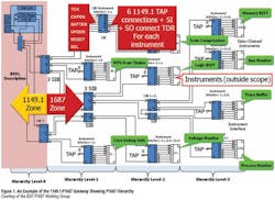
P1687 applies to instruments on one side of a gateway area that has its other side connected to a hardware access section. Initially, that access mechanism will be 1149.1 JTAG but theoretically could be any suitable I/O arrangement that could pass commands and data to the gateway area as well as receive data from it. As shown in Figure 1, the gateway is the interface between P1687-controlled instruments and the IC’s 1149.1 registers.
Tool command language (Tcl) is a dynamic or scripting language in contrast to system programming languages such as C++ and Java. Dynamic languages such as Tcl, Perl, and Python emphasize integration and extension. Tcl is used with the Tk toolkit that supports hypertext linking as well as development of displays with graphics used in GUIs.
According to an article on the Tcl Developer Exchange website, “Tcl is an ideal language for automated hardware and software testing, and it may well be the dominant language used for this purpose. With Tcl, you can easily connect to testing hardware or internal APIs of an application, invoke test functions, check the results, and report errors. Tcl’s interpreted implementation allows tests to be created rapidly, and the tests can be saved as Tcl scripts to reuse for regression testing.”5
A test script based on register names and mnemonics, with commands glued together by Tcl, is appropriate for a given DFx structure within a variety of IC targets. In contrast, test vectors depend on actual scan-chain lengths.
BSDL is used to describe the test registers in the IC being tested, and BSDL extensions allow the description of subregisters. They can have meaningful names, and noncontiguous register bits can be grouped. Nevertheless, BSDL extensions accompany the basic BSDL IC description.
The P1687 working group proposes an extension to BSDL that would access a higher-level instrument connectivity language (Icl) file. This Icl file can more completely describe an instrument’s capabilities and is separately reusable. Anytime the same instrument is included in a design, the same Icl file can be used to describe it.4
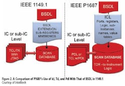
The third proposed language change adds a procedural definition language (Pdl) that describes how to communicate with an on-chip instrument via an 1149.1 TDR. Pdl Level-1 would extend Tcl with Pdl Level-0 commands—the basic commands necessary to interact at the instrument interface level. This means that Pdl Level-1 would be a programming language with variables and data structures as well as commands dealing with program flow. Figure 2 relates P1687’s use of Tcl, Icl, and Pdl to the role of BSDL in 1149.1-based testing.
Some aspects of P1687 remain unsettled although several alternative solutions are being considered in each case. For example, one way to communicate with a number of instruments is to establish a like number of segment insertion bits (SIBs) in the P1687 scan chain. Each SIB is part of the gateway area and associated with a particular instrument’s interface register. Serially shifted command bits are transferred in parallel to the instrument, and the results loaded in parallel from the instrument are serially shifted out. Clearly, this operation is very much in the spirit of 1149.1 and can be extended to support a hierarchy of interfaces.
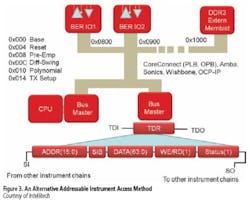
An alternative implementation, shown in Figure 3, assigns a base address to each instrument and reuses the on-chip functional buses that already are present in the design. The 1149.1/P1687 gateway becomes a relatively short TDR comprising address, data, and read/write fields within the serial register. This register would be concatenated with other TDRs of directly accessible instruments such as logicBIST and memoryBIST that are not connected to the functional bus.
Several embedded instrumentation schemes very similar if not identical to P1687 proposals already have been implemented by players in the semiconductor and test industries. However, without a standard, the major benefit of interoperable JTAG-based tools is missing.
Related Activities
FPGAs
Instruments aren’t only appropriate to conventional ICs, but also can be very advantageous when integrated into an FPGA design. For several years, Xilinx and Altera have supported on-chip instrumentation. For example, the Xilinx datasheet for the company’s ChipScope Pro™ Integrated Logic Analyzer states, “The ChipScope Pro…core is a customizable logic analyzer core that can be used to monitor any internal signal of your design.”
The ICON core interfaces to the ChipScope Pro on one side and to a MicroBlaze™ Debug Module (MDM) register on the other. In that sense, the ICON core acts as a gateway. It communicates with the MDM register using serial test data-in and test data-out lines as well as a number of dedicated control signals.
FPGAs are becoming increasingly popular as their capabilities grow. However, because they are dynamic and the proprietary application program IP must be loaded at power-up, unique security issues exist. Altera’s Cyclone III LS FPGAs are examples of devices that include antitamper circuitry specifically developed to counter these threats.
These FPGAs encrypt the configuration bitstream using a volatile key that cannot be read back. Also, the key itself is encoded as several bits distributed among the IC’s logic and stored under layers of metal and can be erased if tampering is detected. In particular, operation of the JTAG port has been restricted to the minimum necessary for 1149.1 compliance. It can be reset to allow full access, but doing so automatically erases all configuration code as well as the security key.
According to Intellitech’s website, the company offers downloadable IP instruments called TEST-IP for testing FPGA SERDES and DDR memory connections at-speed via 1149.1. Embedded test is taken a step farther by adding the tests to the PCB via an IC called SystemBIST.
CEO C. J. Clark commented, “Earlier this year, Applied Signal Technology successfully used our BERT-IP to test 132-Gigabit SERDES channels at-speed. Our SystemBIST IC embeds the tests, stores the failures, and manages remote updates in the field.”
As described on the company’s website, “The TEST-IP Family leverages the 1149.1 industry-standard test bus as a single unified [configuration and test data] application vehicle. This unified approach to configuration and test lowers manufacturing test costs, simplifies field support, and extends a product’s useful life. The TEST-IP infrastructure IP is scalable and can be reused during all phases of the product life cycle and from one product design to the next.”6
Mr. Clark explained that Intellitech also has taken steps to jump-start adoption of P1687 techniques by providing the NEBULA software package for free. NEBULA is the company’s platform for development of Icl, Pdl, and Tcl/Tk for P1687. The developer can validate the instrument Pdl against a Verilog compiler simulation (VCS) of the instrument or an implementation of the instrument in an FPGA using a Xilinx JTAG Pod.
National Instruments (NI) provides customizable application-specific hardware via the NI FlexRIO FPGA Modules and adapter modules together with the LabVIEW FPGA graphical programming environment. Raajit Lall, the company’s product manager for high-speed digital I/O, commented, “Adapter modules interface the UUT to the user’s proprietary configuration code loaded into a Xilinx FPGA. NI and Xilinx also provide embedded FPGA IP such as pattern comparators and pseudorandom bit generators for BIST capabilities.”
The FlexRIO product is a good example of how FPGA–based test instrumentation can be developed. On the other hand, NI’s definition of embedded test is somewhat different from that used by electronic design automation (EDA), boundary scan, and semiconductor companies. To NI, embedded test also relates to the company’s long-standing focus on PC-based, software-defined instrumentation with the slogan “the software is the instrument.”
In an ATE-related example of an embedded test application, Mr. Lall explained that “NI has collaborated with Test Systems Strategies to create the TD [TestDeveloper]-Scan for NI software tool that seamlessly integrates files generated from Cadence or Mentor Graphics design tools into PXI-based testers. This tool enables the use of waveform generation language (WGL) and standard test interface language (STIL) patterns with NI high-speed digital instruments.”
1149.7
The most recent addition to the list of 1149.x standards is 1149.7, compact boundary scan or cJTAG, which preserves 1149.1 compatibility while extending the original standard’s capabilities. Its features were described in a recent EE-Evaluation Engineering article:7
So-called zero-bit data register (DR) scans (ZBS) are counted to determine the intended control level. A ZBS “begins at the Select-DR-Scan state and proceeds to an Update-DR-TAPC state without an intervening Shift-DR-TAPC state.”
The control level selected corresponds to the number N of ZBSs counted before encountering a Shift-DR command. When one is encountered, further commands are interpreted as level-N instructions. Obviously, a control hierarchy can be created based on this mechanism, and 1149.7 has established one with six classes.
A large number of features can be controlled via this structure including four power-down modes, various bypass scenarios, and unambiguous star network communications. Two further capabilities, however, have proven to be the new functionality most often referred to:
“Class T4 adds scan formats to support transactions with two pins instead of four…sending bidirectional serialized data over the TMS line which is renamed TMSC…. Class T5…gives the test port the capability to concurrently perform debug and instrumentation operations, which reduces the number of pins dedicated to instrumentation.”
Company Initiatives
The confluence of 1149.7 Class T5 instrumentation access, FPGA IP instrumentation cores, BSDL extensions and in particular extensions via Pdl, and ongoing P1687 progress indicates the importance of embedded instrumentation. It also shows the diversity of the topic and reflects the different emphasis various companies have placed upon it.
Goepel Electronics’ Heiko Ehrenberg, managing director U.S. operations and a P1687 working group member, said “Our technology is primarily based on device access through the TAP defined in IEEE 1149.1. We communicate test and instrument control patterns to target devices through the JTAG chain. With this access, we also can control BIST, of course assuming the BIST instruments are accessible through the JTAG infrastructure.”
A capability that Goepel has been promoting is concurrent handling of boundary scan and JTAG emulation vectors through the VarioTAP product. The company claims that VarioTAP merges the handling of emulation tests and boundary scan tests, supporting direct interaction between the two.
According to a Goepel white paper, “The VarioTAP models are structured as modular IP and provide a behavioral definition of certain microprocessor functions used in different VarioTAP applications…. Respective device models are to VarioTAP what a BSDL file is to boundary scan…multiple VarioTAP models can be active at the same time.”8
ASSET InterTech recently changed the company’s tag line from “The Boundary Scan Company” to read “Driving Embedded Instrumentation.” That’s a clear indication of how it views the future of embedded test, which the company broadly terms nonintrusive board test (NBT).
Glenn Woppman, president and CEO, commented, “ScanWorks® is a platform for multiple embedded test technologies, including boundary scan/JTAG test, PCT, and Intel interconnect built-in self test (IBIST). Other tools will be integrated into ScanWorks in the future, such as tools to support IJTAG P1687 for accessing, automating, and analyzing the output of embedded instruments. Because of the wide range of embedded test technologies supported by the ScanWorks platform, a large variety of BIST can be handled including memory, logic, and I/O BIST.”
Mr. Woppman also discussed the importance of embedded instrumentation in the narrow sense of being entirely self-contained as often is the case for high-reliability systems. The embedded test capabilities are used to determine the root causes of faults, failures, or performance degradations as well as provide remote diagnosis. Obviously, if a technician knows precisely what has gone wrong, it can be quickly repaired. Understanding the root causes of the problem allows the design to be corrected so there are no further occurrences.
According to the company, in an example of this type of requirement, “Cray is embedding ScanWorks-based test logic to support remote diagnostics in the company’s supercomputers. The ScanWorks IP provides fault isolation through capabilities such as single and multiprocessor bring-up, remote test, kernel dump, hung system debug, and breakpoints.”
JTAG Technologies’ President Peter van den Eijnden explained, “JTAG Technologies primarily focuses on board-level applications. Sometimes, embedded instruments such as BIST and microprocessor emulation/debug registers also are included although often we find that the absence of a boundary scan register unnecessarily makes board-level testing more complex and expensive than necessary.
“With regard to new embedded instrumentation standards being developed,” he continued, “we hope device manufacturers adding these elements to their SOC devices also will include a basic boundary scan register. This will make structural testing at the board level as well as the system level possible.”
An article on the JTAG Technologies website presents the concept of linking “high-level JTAG functional test (JFT) access routines… [into] the open-source Python language…. Entire device-level test routines can be created and saved without reference back to the boundary scan pins that provide the stimulus and response signals. This makes them portable and reusable across designs and projects.”9
Conclusion
It’s apparent that embedded test instruments are being used today in many designs. Equally apparent is the lack of a unifying standard to govern their use. Similar embedded instrumentation themes run through the activities and products of EDA, FPGA, instrumentation, and boundary scan companies, but each implementation is different.
From a set theory viewpoint, the best standards are based on a union of relevant expertise, and in this case, that resides in many related areas. Taken in the sense of joining, it’s time for the P1687 working group members to agree on a suitable standard. 1149.1 didn’t solve every outstanding problem, nor did it anticipate each technological advance that over time prompted additional 1149.x capabilities. Nevertheless, the embedded test benefits enjoyed today stem from wide adoption of 1149.1.
References
1. Parker, K. P., The Boundary-Scan Handbook, Kluwer, 1992.
2. “Boundary-Scan Tutorial,” ASSET InterTech, 2009, pp. 68, www.asset-intertech.com/registration.cfm?/nk=primer
3. www.corelis.com/products-JTAG/ScanExpress_JET.htm
4. Clark, C. J. and Tuthill, B., “Introduction to IEEE P1687/IJTAG,” Intellitech, presented at North Atlantic Test Workshop 2010.
5. http://www.tcl.tk/about/features.html
6. www.intellitech.com/products/boundary_scan_test.asp
7. Lau, S., “IEEE 1149.7 Expands JTAG Functionality,” EE-Evaluation Engineering, July 2009, pp. 44-49.
8. Ehrenberg, H. and Wenzel, T., “Combining Boundary Scan and JTAG Emulation for Advanced Structural Test and Diagnostics,” Goepel Electronics.
9. Stanbridge, J., “Boundary Scan for Functional Test,” Embedded Systems Design Europe, February-March 2010.
| FOR MORE INFORMATION | Click below | |
| Altera | Cyclone III LS FPGA Family | Click here |
| ASSET InterTech |
ScanWorks
|
Click here |
| Corelis | JET JTAG Embedded Test | Click here |
| Goepel Electronics | VarioTAP | Click here |
| Intellitech | SystemBIST TEST IP | Click here |
| JTAG Technologies | JTAG Live PCB Debug Tools | Click here |
| National Instruments | FlexRIO FPGA Module | Click here |
| Xilinx | ChipScope Pro Logic Analyzer Core | Click here |
About the Author
Comment About the Article
To join the conversation, and become an exclusive member of Electronic Design, create an account today!

Leaders relevant to this article: