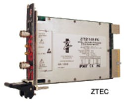
For some time following their introduction, arbitrary waveform generators (Arbs) tended to be products looking for applications to address. Certainly, there were problems for which an Arb was the best technical solution but often not the most economical. Today, it’s difficult to see how many types of test signals could be generated in any other way.
Two very different architectures traditionally have been used for Arbs, each with distinct capabilities. The most obvious way to create an arbitrary waveform is to store data in a memory that is sequentially read out into a DAC. With a bit of filtering, a waveform is generated that directly reflects the stored data values.
To speed up or slow down the output rate, the clock driving the memory must be varied, which has practical limitations. At very slow speeds, the DAC output will remain stationary for relatively long periods of time. At very high speeds, the technology used to implement the digital circuitry and DAC will limit performance.
Slow-speed operation can be improved somewhat by using a much larger memory and greater vertical resolution. A 16-bit DAC supported by a very long memory is feasible and economical. Very high-speed technology is expensive so Arb products have become specialized in the same way as digital oscilloscopes. A few high-speed units are available but you wouldn’t choose to use them for general-purpose work.
Output reconstruction filtering is very important because all Arbs are sampled data systems. Reconstruction filters usually have a low-pass characteristic to remove signal components typically higher than 45% of the sampling rate—slightly less than the Nyquist frequency. For variable clock rate Arbs, the filter characteristic must track the clock rate.
The other architecture is based on the direct digital synthesis (DDS) technique that is most easily explained assuming a fixed frequency clock. In this approach, a long memory is filled with data values representing one cycle of the desired waveform, and the data is output through a DAC, much as in the other method.
The difference is in the way that the memory address is calculated. The clock drives a phase accumulator, which is an adder with many more states than the number of memory locations. A typical example would be a 40-bit phase accumulator and a 4,096-location (12-bit) memory.
On each clock pulse, the phase accumulator adds the value in the phase increment register to the total. Typically, the phase increment register will be similar in length to the phase accumulator. Many texts call the value in the phase increment register the tuning word.
In this example, only the 12 most significant bits (MSBs) of the phase accumulator are used as the memory address. If the tuning word value is exactly 228, the phase accumulator adds a least significant bit (LSB) to the 12 MSBs on each clock pulse, and the system acts precisely like the other architecture. Each memory location is read out in sequence, one location per clock pulse.
However, consider what happens when the phase register value is larger. At 229, the output frequency doubles, but every other memory location is skipped. Because the skipping is evenly spaced, it may not cause a problem for filtered sine wave generation. But if an arbitrary waveform contains a narrow spike, this method of operation can easily miss the spike if the spike data value happens to be stored in a skipped location.
The great benefit of a DDS system is its capability to generate signals with very high-frequency resolution by setting a suitable tuning word value. Point-by-point Arbs don’t skip points, but neither do they present the precise on-the-fly speed control opportunities of DDS-based Arbs. In a DDS design, it’s possible to vary the tuning word to directly and phase-continuously modulate the generated waveform even for large frequency hops. On the other hand, point-by-point Arbs always output from each memory location so the memory can be segmented. This capability leads to programmable sequences of segments each repeated a selectable number of times.
DDS Clock Generation
Clock noise of all kinds will contribute to Arb output noise so a jitter-free, constant amplitude clock source is desirable. Unfortunately, a DDS system inherently is noisy because of the truncation that occurs in the phase accumulator and DAC quantization errors.
Many DDS systems are used as sine wave sources so the value of the phase accumulator can be thought of in relation to 360° of phase in one cycle of a sine wave. Assuming a constant tuning word, the phase accumulator values will increment linearly with each clock. But when only the MSBs are used to address the waveform memory, errors occur because of the truncation.
Depending on the tuning word value, phase accumulator truncation can cause the output spectrum to contain spurious frequencies with significant amplitudes. It’s easy to see that if the tuning word is very large, then few of the stored data points are output each cycle. In addition, unless a large tuning word value evenly divides into the memory length, different points will be skipped on successive cycles.
Under these conditions, the resulting waveform from the DAC is very rough and resembles a sine wave primarily because you know it should. For these waveforms, the term reconstruction filter takes on greater meaning. A sharp cutoff filter with a bandpass close to Nyquist will recover the sine wave fundamental and reject higher frequency reconstruction images and harmonics.
An example DDS system in an Analog Devices DDS tutorial had a 175-MHz clock rate (5.7-ns period) and was generating a 56-MHz output waveform.1 Only about three samples per cycle were being output. Because so many points were being skipped as well as different ones output in each cycle, the jitter was a full clock period. In fact, one clock period is the worst-case jitter that occurs in a DDS system for a constant tuning word, but clearly 32% of the 56-MHz output’s 17.8-ns period is very high.
A common technique applied to DDS DAC outputs used as system clocks is to filter the output to create a pure sine wave and then generate a square wave from the sine by using a comparator. In the example, a 65-MHz seventh-order low-pass elliptical filter reduced the jitter to less than 250 ps. Achieving very low levels of jitter and noise depends on all the parts of a DDS system as well as layout. Nevertheless, the reconstruction filter is a critical part.
Filtering
When a DDS system is used as a clock generator, a pure single tone is required. This specification relates best to the frequency domain where one spectral line represents a single frequency. A sharp cutoff filter minimizes the distortion to the fundamental clock frequency. Of course, a sine wave clock has slow edges so a comparator is used to sharpen the edges to provide precise timing.
This approach doesn’t work for arbitrary waveforms because generally they are defined in the time domain. In this case, the reconstruction filter’s transient characteristics are more important than its frequency discrimination capabilities. Filters that best preserve time-domain waveform shapes have very gradual stopband attenuation rates. Typically, a Bessel filter with maximally flat group delay or an equiripple group delay filter will be used to approximate a Gaussian response.
Exactly which filter is used depends on how much phase nonlinearity or group delay ripple can be accommodated. The Analog Devices DDS tutorial recommends an equiripple filter “for wideband applications in which group delay must be controlled over the entire band of interest. Like other Gaussian filters, the phase response is mostly linear with minimal overshoot or ringing.”
Observations and Trends
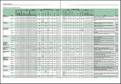
Technical specs for several Arbs from many companies are listed in the comparison chart accompanying this article. Although the generators have many similar aspects, there are important distinctions. For example, are you limited to the maximum clock frequency an Arb may provide? Yes, but the answer’s not straightforward. Several newer Arbs offer interpolation, which multiplies the sampling frequency by a factor of x2, x4, or x8 and smoothly interpolates your original waveform data so it will generate the same signal at the new higher sample rate.
On the surface, this seems like two steps forward and two steps back. Interpolation can’t add accuracy to the original data but instead it is done to shift the DAC output images to higher frequencies. Of course, there also are times when you simply need to generate data at a higher rate. Interpolation retains the original signal bandwidth. Because the images have been generated at higher frequencies, filtering can achieve a higher SNR than without interpolation.
Also, some instruments include digital upconversion hardware that supports direct modulated RF. The arbitrary capabilities are used to develop closely synchronized I and Q channels of baseband information that then modulate an RF carrier—all in one generator.
Click image to enlarge.
Datasheet Clues
Good clues to a generator’s operation can be found in the datasheet. If different types of filters are listed, a distinction is being made between sine and arbitrary waveforms. Sine waves benefit from the extremely fine frequency resolution of a DDS system but require a very sharp cutoff reconstruction filter.
Another clue is in the frequency range specification. Because of the sharp cutoff reconstruction filter, sine waves can be generated at rates close to Nyquist. Any other wave shape will have a much lower maximum frequency. This is a typical characteristic of a DDS-based generator. Be careful not to confuse the square wave rise/fall time with the rise time of an arbitrary waveform. The square wave may be generated by a comparator so often it has a separate and different specification.
Point-by-point designs don’t really have a meaningful frequency range. Instead, because the waveform is defined in the time domain, the sampling rate is quoted along with the allowable memory size. If you need fine time resolution, a long memory length played out at a very high sampling rate is a much better choice than a similar wave shape stored in a short memory read out at a slower rate. Either approach may generate the same fundamental frequency but one will include more detail at higher frequencies than the other.
Additional insight into an Arb’s frequency range is given by pulse specifications. A minimum one- or two-sample-clock pulse width may be quoted although the usefulness of a narrow pulse depends on the filter selected. For some instruments, even the highest frequency Bessel filter selection may significantly attenuate a very narrow pulse.
As is the case with many types of instruments, the quality of Arb datasheet information and its presentation vary greatly. The best datasheets are those that simply set out the characteristics of the generator, making clear how the various modes interact. If both DDS and point-by-point modes are available, describing each set of parameters in separate sections is easier to understand than some form of combined specification.
Some generators describe the source of standard waveforms as internal. Is this really true? Is there on-board nonvolatile storage for these waveforms? In many instruments there is, and some datasheets actually state that a Flash memory is used. In other cases, the waveforms become internally stored only after definition in a software application and subsequent download. Ultimately, the signal generation capabilities may be similar for both Arb implementations, but how you interact with the instruments certainly is not.
It’s particularly difficult to determine the time-domain characteristics for generators that are described by a frequency-domain-oriented data sheet. Nevertheless, all the instruments included in the comparison chart have Arb capabilities, and most state that the Arb output is developed point by point. Of course, it’s possible that a datasheet’s areas of greatest clarity may indicate those things that the generator does well.
The Tektronix phrase is meant to contrast with the complicated and very indirect way in which RF signals typically have been synthesized in the past. RF synthesizers take different forms but often generate the desired signal through repeated mixing and filtering—hence, the use of direct to contrast with indirect.
The DDS approach was first described by Tierney and colleagues in the 1971 paper “A Digital Frequency Synthesizer,” published in the IEEE Transactions on Audio and Electroacoustics. To add some historical perspective, Robert Moog already had sold several music synthesizers by the mid-1960s and in 1968 instantly became famous upon Columbia Record’s release of the Switched-on Bach album featuring one of his synthesizers. The unique sound of the Beatles’ “Here Comes the Sun” from their 1969 Abbey Road album also came from a Moog synthesizer.
Compared to the network of analog voltage-controlled oscillators and amplifiers that Moog developed, Tierney’s approach truly was direct digital synthesis. Tek’s choice of terminology is unfortunate although in actuality it may be less confusing than it appears. It’s really a question of how RF engineers understand what Tek means and how time-domain engineers, who use synthesized function generators, understand Tierney’s meaning. As long as the overlap between the two groups is small, so too will be the confusion of the terms.
Applications and Conclusion
A wide range of technologies is represented in today’s Arbs including pure DDS, pure point by point, and mixes of the two approaches. A quote from the EADS North America Test & Services 3152B datasheet highlights the complexity availability in modern signal generators. “The…3152B provides a synergistic combination of a swept function generator, pulse generator, programmable sequencer, and arbitrary waveform synthesizer into one instrument. In addition, the 3152B integrates a phase locked loop, modulation, sweep, hopping (amplitude and frequency), and a high-performance frequency counter into a single-slot VXI module, saving valuable space.”
It’s good to have lots of capabilities so that one instrument can satisfy several distinct application-specific requirements. Nevertheless, a number of basic questions can be answered upfront to help narrow the range of possible solutions:
• Do you need to output each point in the waveform data?
• How much detail is necessary?
• How fast must the waveform be generated?
• Is phase coherence or hopping important?
• How many channels are required?
• Are the channels independent or linked?
Several other questions may be suggested by a number of actual applications.
GW Instek’s Model AFG-3000 has a 1-Mpoint memory and was used by one customer to generate 1% and 20% duty-cycle pulses referenced to periods of 2 µs, 10 µs, and 1,000 µs in length. All six waveforms can be stored within a single 1-M memory and selectively output.
Tek’s Gregory Davis, product manager for the source analyzer product line, explained, “Customers still are asking for more bandwidth. High-speed serial data rates are pushing 12 Gb/s and 16 Gb/s, and customers want higher sampling rates to achieve the one-box impairment control that Arbs can provide.”
Ryan Verret, signal generators product manager at NI, described a mixed-signal semiconductor test: “This device had an IF input along with on-board ADC, demodulation, and decoding. Testing the chip’s algorithms along with its analog performance required continuous generation of high-frequency signals for hours on end. This was achieved by streaming data from a RAID array at up to 400 MB/s to the NI PXIe-5442 Arb.”
Agilent’s Thomas Dippon, product planner and application expert, related a test example that involved “simultaneously generating 70 digitally modulated carriers up to 1.5 GHz for testing digital TV antenna amplifiers. The Arb generates a direct RF signal and was controlled by a MATLAB program. We achieved 1-dB flatness up to 1 GHz and about a 50-dB noise power ratio,” he said.
For most applications, many Arb models may be capable of satisfying the requirements. Unfortunately, it’s not always possible to understand important differences among a group of generators just by reading the datasheets. And, as some of the example applications imply, there are more parts to a test system than just an Arb. Development of the test signals is not trivial, whether the signals are based on MATLAB or one of a number of manufacturers’ proprietary software programs.
The best approach is to borrow an Arb and try it in your application. Start small with a simple example program that you can easily verify. Record signals on your DSO, download them to the Arb, play them back, and compare them. With many Arbs available, your time can be spent making an informed choice rather than searching for products.
Reference
1. “A Technical Tutorial on Digital Signal Synthesis,” Analog Devices, 1999, http://www.analog.com/static/imported-files/tutorials/450968421DDS_Tutorial_rev12-2-99.pdf
