A switching matrix used in a test system connects a signal on a particular column to an instrument on a certain row. Typically, there are more signals than instruments, so several voltage measurements might be made by successively connecting a DMM to different points in a circuit. The number of rows N and columns M defines the size of the matrix as NxM. By convention, rows are listed before columns.
Several terms are used to describe matrices. Crossbar or crosspoint switching is a general description that originated in electromechanical telephone switches that literally used groups of metal bars in both the X and Y directions. Depending on how the contacts were arranged between the NxM bars, more or fewer circuits could be simultaneously supported.
A matrix that allows every input to be connected to a separate output is described as nonblocking and can be very helpful in complex test systems. Jeffrey Lum, chief technical officer at Giga-tronics, clarified this definition, “For an IxPxO matrix, where I is the number of inputs, O is the number of outputs, and P is the number of simultaneous paths, when P = I, the matrix is nonblocking.”
Clearly, when P is less than I, not all the inputs can connect to an output, and one or more inputs are blocked. As logical as this description appears, nonblocking and blocking are not used to mean the same things by all manufacturers. Some of the inconsistency is historical.
Nick Turner, CEO at Cytec, provided interesting background information, “Early on, when telephone companies were attempting to replace manual patch panels and switchboard operators with automated switching, the term blocking was used to describe a low-cost type of switch matrix that had a high probability of making a phone call without disconnecting any other call or giving the dialer a busy signal.
“The problem was one of accommodating perhaps 5,000 people that simultaneously needed to make a call from among a total of 100,000 telephones,” he continued. “Rather than build a huge nonblocking matrix to handle any number of calls, the solution was to make a blocking matrix that only allowed up to 5,000 people to be connected at the same time. The more you reduced the switch count, the smaller and less expensive the system became, but with a higher probability that you would get a busy signal because a path was not available.”
Some companies use blocking to refer to matrices that have sufficient switches to connect every input to an output, but you will need to disconnect all the paths to make changes to the connections. Other manufacturers use blocking to indicate that all inputs cannot be connected to outputs at the same time. Still other companies limit the number of simultaneous paths to one. So, although blocking implies a restriction, its severity is not standardized.
Nevertheless, as Mr. Turner commented, if your test system can be designed to run a test, reconfigure the switch, and run the next test, a blocking matrix may save lots of money compared to a nonblocking implementation. Mr. Lum added that blocking matrices often are used for high current switching. In these applications, blocking helps prevent unintended connection of multiple resources and devices.
Charles Greenberg, senior product marketing manager at EADS North America Test and Services, concurred, “Blocking matrices can offer improved performance over a crosspoint type nonblocking matrix in terms of shorter stub length for better AC characteristics and better expandability of its dimensions for the density and price. This technique is applied when multiple paths are required but not all possible paths from channels N to M are needed simultaneously,” he concluded.
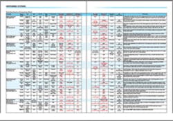
The comparison chart accompanying this article lists many matrices from several companies. The terminology used to describe each product is consistent with the datasheet or information provided by the manufacturer.

Switching Systems Comparison Chart.
Click image to enlarge.
Further Matrix Flavors
Mathematically, a sparse matrix is mostly filled with zeros. Accordingly, the term is used to describe a switching matrix that allows any row to connect to any column, but only one or a few of each at a time. By definition, a sparse matrix is blocking. For one circuit, the configuration can be implemented as a pair of back-to-back multiplexers. The first multiplexer selects one of N inputs, and the second multiplexer directs that input to one of M outputs.
The National Instruments (NI) PXI-2593 and SCXI-1193 RF Switches can be configured as any 18-terminal or any 36-terminal sparse matrix, respectively. Figure 1a represents the routing possibilities within the PXI-2593 module. Paths cannot cross red lines but can cross black lines. Only one path can be drawn through any closed space on the diagram. Figure 1b shows how four simultaneous paths are supported. However, using the module resources in this way blocks terminals COM1, 1, 3, 5, 6, 7, 11, 13, 14, and 15.
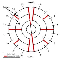
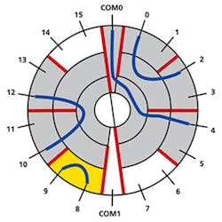
Figure 1a. PXI-2593 Sparse Matrix Routing Resources Diagram
Figure 1b. Four Routes Established Through PXI-2593
Courtesy of National Instruments
Another phrase that describes a matrix is full access, which many companies use to mean that an input can be routed to any or all outputs. This definition has several implications depending on the frequency range and application. For low-frequency signals driving high impedance loads, inputs can be distributed to multiple outputs with little degradation. Simultaneously connecting a power supply to several matrix outputs often is required. In a semiconductor test application, many pins may need to be grounded to isolate a specific diode when measuring IC protection diodes.
Giga-tronics’ Mr. Lum explained the full-access term with reference to a nonblocking matrix, “Nonblocking allows any resource to connect to any device, but a resource can connect to one device at a time. In a full-access matrix, a resource may be shared with multiple devices.”
In contrast, Agilent Technologies and Universal Switching call an NxM matrix with N paths formed from back-to-back multiplexers or multiport switches a full-access blocking matrix. Offering yet a different definition, Keithley Instruments’ Paul Meyer, senior staff technologist, said, “A blocking matrix allows the connection of a single input to a single output. Therefore, only one signal path is active at any given time. A nonblocking matrix allows simultaneous connection of multiple input/output signal paths.”
To create multiple copies of an RF or microwave signal, a power splitter must be used. Each of the splitter outputs then can be selected by an output.
Dow-Key Microwave’s Sara Nazemzadeh, an applications engineer at the company, explained, ”Nonblocking solutions such as a fan-out matrix provide more flexibility because any input can fan out to multiple outputs simultaneously and divide the input power to multiple switch outputs…. The trade-offs are low isolation between output ports connected to the same input and restricted bandwidth caused by limitations of the power dividers/combiners. This approach is best suited for applications with limited bandwidth such as fan-out downlink and receiver sites and fan-in and transmission sites.”
Buffer amplifiers only operate in one direction, so matrices that include them aren’t bidirectional. In contrast, matrices built only with electromechanical relays are bidirectional. Passive power splitters generally are bidirectional, working as either splitters or combiners. Active power splitters usually are not bidirectional.
Control
Configuration
Most test applications don’t intentionally connect more than one input to a single output although this is what is meant by reference to RF signals fanned-in to a power combiner. For the kinds of matrices usually encountered in test applications, manufacturers provide configuration software that helps you define which switches should be open or closed for each test.
One of the software program’s capabilities is identification of possibly damaging switch combinations, such as two power supplies connected together or a signal connected to a power supply. Sometimes, hardware interlocks are used as an additional safety precaution when high voltages are involved. However, in most cases, it’s up to you to ensure that only the desired connections occur.
Cytec’s Mr. Turner said the company “has always taken the attitude that the engineer using the system knows what he wants to do and can write protection into the software if desired. We do provide both front-panel LED indicators and full status feedback so the state of any relay can be checked before proceeding to the next configuration, and we encourage people to make use of these protection features when they write test code.”
Mr. Greenberg explained that the EADS switches often are driven by smart controllers, which afford additional opportunities for monitoring switch combinations. “Exclude/include lists and paths can be defined to prevent the creation of potentially damaging paths. And when safety is an issue, interlock features are provided,” he said. “For example, the 1220 family of 16-A LXI switch plug-ins is provided with an emergency shutdown input that allows the user to manually or automatically open all power switches.”
Keithley’s Mr. Meyer said, “Model 3706 Switch System/Multimeter modules have hardware interlocks designed to keep the switching modules disconnected from the system backplane. To engage the hardware interlocks, the user must provide a low resistance path between the two interlock pins. This path routes a 5-V power source to an on-board interlock relay that enables power to the backplane relays.”
It’s easy to get caught up in test program implementation details, but before buying any switching solution, you may wish to consider how it behaves when the power unexpectedly fails. Many matrices are based on latching relays. When powered normally, latching relays can be a great advantage because they only require a short pulse to change states. On the other hand, should power fail, the last configuration will be retained until power again is applied.
In the event that power was lost coincident with applying pulses to the relays, you have no way to guarantee what state the relays will be in when power is next applied. Nonlatching relays require constant power to keep them activated, but should the power be lost, they all will revert to their nonactivated state. For most matrices, this is an open circuit.
Maintenance
Relay operation counting is built into many matrices. Because relays have a finite life, knowing how many times a relay has been operated can help improve reliability. But, it’s not as simple as replacing any relay that has reached more than a certain number of make/break cycles.
Two wear-out factors are at work in a relay. One is the mechanical degradation that occurs from repeated opening, closing, and flexing of the contacts and supporting structure. The purely mechanical lifetime for some relays is listed as >100 million operations. Contact pitting and contamination are much more often the causes of relay failure and may occur after only 100,000 operations or even earlier. It all depends on the relationship between the relay and the signal it switches.
In so-called cold switching, current and voltage are very low or zero so that relay lifetime approaches the mechanical limit. After the new switch configuration has been established, the signal is applied. In contrast, hot switching simply interrupts the signal and often results in arcing and contact wear. Nevertheless, as mentioned in Keithley’s Switching Handbook, a relay designed to handle large currents may require a certain amount of switching current to keep the contacts clean.1
Relay operation counting allows you to balance relay usage. For example, a test program may work correctly but unnecessarily open several relays between test steps only to immediately close them again for the next test. A review of relay counts can highlight this kind of problem, allowing simple but beneficial test program changes.
Because the switched signal plays so great a part in determining a relay’s lifetime, several manufacturers have developed built-in relay test capabilities. Much more comprehensive than counting the number of operations, these test routines find relays stuck open or closed as well as those with high contact resistance.
The NI Switch Health Center included with the NI SwitchBlock incorporates an integrated relay test and can access relay count information. The test algorithm identifies each relay as functional, stuck open, stuck closed, or unverified because of board faults that prevent thorough testing. Pickering’s built-in relay self-test (BIRST) tool offers similar functionality.
Other Considerations
Fidelity
RF and microwave matrices typically maintain a 50-? impedance and route signals on transmission lines. This means that when a switch pole is open it must be terminated to avoid creating reflections, and many matrices include terminating resistors for this reason.
The need for relatively large electromechanical switches at microwave frequencies increases the difficulty of maintaining signal fidelity through multiple levels of switching. Mike Dewey, senior product marketing manager at Geotest Marvin Test Systems, favors blocking matrices for this reason. “[Multiplexers, star switches, and blocking matrices] all generally offer better bandwidth and crosstalk performance compared to a general matrix topology. For higher frequencies of interest or if you are looking for a controlled impedance path, these types of topologies probably are a better choice,” he explained.
Further elaborating on matrix construction, VTI’s Jon Semancik, director of marketing, said, “Anytime a crosspoint matrix is used, path stubs introduce reflections. However, tree-based matrices do not create stubs and are well suited to RF and microwave switching. VTI’s modular switching systems, such as the LXI EX1200 Series, are scalable so that larger matrices can be constructed by adding more matrix modules. We break the modules into multiple smaller matrices by using stub-breaking relays to improve frequency performance.”
Expansion
The easiest matrices to expand are those that have been designed with an internal analog bus. NI’s SwitchBlock, Keithley’s Model 3706, VTI’s EX1200, Pickering’s BRIC, the EADS 1800 Series, and Giga-tronics 4000 Series matrices are examples of multimodule designs. Mechanically, most of these products comprise an outer chassis into which the various matrix modules are plugged. This approach has the advantage of creating a large matrix with only one system address but the disadvantage of proprietary modules.
There are other expansion possibilities. Geotest’s Mr. Dewey observed, “One way to expand is simply to daisy-chain the X or Y side of the matrix. However, performance of the overall matrix can be limited. A better way is to use a matrix with bypass and matrix-disconnect relays that significantly reduce stubbing effects and help to maintain signal bandwidth.”
Agilent’s Ms. DeTomasi explained how these kinds of capabilities are implemented in the company’s 34934A Matrix: “This matrix is specifically designed for expansion with minimal impact on signal integrity. It features row expansion cables to minimize wiring between multiple modules. Additionally, to keep the capacitance low, the 34934A uses row-disconnect relays to disconnect the matrix modules not being used.”
Summary
A very wide range of matrices is available to address almost any application. Of course, the challenge is to find the optimum solution from among the many that are possible. It can be complicated.
Bob Stasonis, sales and marketing manager at Pickering Interfaces, cautioned that matrices share the same constraints associated with all relay applications. Some requirements are best addressed by solid-state switching, some by electromechanical relays, and yet others by reed relays. To these considerations you must add the specific needs of the test setup. How many simultaneous paths are used? How can the paths be partitioned? What different types of signals must be accommodated?
Mr. Stasonis concluded, “Selecting a matrix is a balance of specifications, form factor, project life, and budget. For all these reasons, customers unfamiliar with the available choices should work closely with the matrix manufacturer of their choice.”
Reference
1. Switching Handbook; A Guide to Signal Switching in Automated Test Systems, 5th Edition, Keithley Instruments, 2006, pp. 4-6.
About the Author
Comment About the Article
To join the conversation, and become an exclusive member of Electronic Design, create an account today!

Leaders relevant to this article: