A Custom Life Test Platform for Aircraft Seating
Simulating a lifetime of wear and tear on aircraft seats requires a scalable hardware and software solution to meet the needs of multiple and diverse test requirements. Each life-cycle test needs specific setup conditions and different instruments and actuators. For these reasons, engineers from G Systems and Recaro Aircraft Seating, a leading manufacturer of aircraft seats, developed a fully customizable control module to interface with a universal life-cycle test fixture for aircraft seating.
Recaro’s many different life-cycle tests use a variety of test instruments and measurement sensors. Because of the variations, the company wanted a test platform that was user friendly, flexible, and easily configurable to control all of its life-cycle testing and data acquisition in one system. The control software needed to run continuously and reliably for weeks at a time and provide real-time monitoring and data display capability.
The Solution
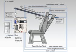
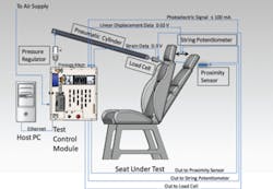
Figure 1. System Diagram
Based on Recaro requirements, G Systems designed and built a universal control test platform using National Instruments compact RIO (cRIO) data acquisition (DAQ) modules. The cRIO industrial computer and DAQ platform provide the analog input, analog output, digital input, and digital output required for the actuators and control sensors such as pneumatic cylinders, photocells, load cells, and string potentiometers. A real-time software control system and hardware platform afforded deterministic testing and the long-term stability needed for life-cycle testing. A separate PC host provided the configuration interface and monitoring for the real-time application. Figure 1 presents an overall system block diagram.
The key to the Recaro test system is a custom script tool that allows the operator to configure inputs and outputs through a GUI. The test station can be set up for many test conditions using multiple sensors and test limits.
System Overview
Recaro Aircraft Seating designed and built a custom aircraft-seat test fixture that ensures the seats have been tested to meet the requirements of its customers. Currently, the company operates four test stations, each consisting of a test fixture, a test control module, and a host PC. The dual-station test fixture allows Recaro to anchor the test seats and connect all of the cylinder hardware and measurement sensors to the control modules.
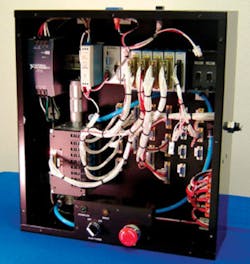
Figure 2. Test Control Module
The control module includes the cRIO computer and DAQ units as well as an air manifold that provides air pressure for up to eight two-way pneumatic cylinders that provide the test forces (Figure 2). The DAQ system accommodates strain measurements and includes analog input and output and digital input and output modules. The control module allocates the electrical resources for life-cycle tests, providing the analog and digital signals necessary for the different instruments.
Whether the test is a simple push/pull or a multi-axis test, the hardware requires no changes—just a different connector setup. Multiple DB connections provide quick access to the various I/O resource channels.
A channel configuration table is used to assign logical names to each resource and define scales for each channel. Where PID control is required, such as maintaining a steady pressure or load, a PID interface is available to determine the tuning constants necessary for a stable, accurate, and safe test. The host PC connects to the control module box through Ethernet on a private network. This PC provides the configuration interface and monitors the real-time application.
The airplane-seat test configuration begins with the seat-under-test setup. The seat is positioned in the fixture to allow the pneumatic cylinder to apply a force to the seat, for example the seat back. The test control module includes a pressure-sensor alarm to warn if the pressure exceeds the test limits. Other tests could be configured for tray-table or armrest life testing, for instance.
Sensors then are placed around the seat for data collection. A photoelectric cell is used as a proximity switch to set the limit for how far the seat back should be pushed. The photocell is powered by a voltage from the NI 9263 Analog Output Module, and the current signal is monitored by the NI 9205 Analog Input Module.
The movement of the seat back is measured by a string potentiometer that measures displacement of more than 1,000 mm. The potentiometer encoder signal is measured by the NI 9205 Analog Input Module and then scaled to convert the voltage to distance.
The strain upon the seat is measured by a load cell mounted in line with the pneumatic air cylinder. The load cell is powered by an external power supply through the NI 9263 Analog Output Module to provide the excitation current required for the bridge transducer. The NI 9237 Analog Input Module returns the measurement from the full bridge resistor. This measurement then is converted to strain based upon the scale factor from the manufacturer.
The system can be configured for a constant strain or pressure using a PID feedback control loop. The output resource can be both digital and analog. The measurement signal or control resource is an analog input signal such as pressure or strain. If the output resource is digital, it will turn on immediately and stay on until the desired input level is reached.
For an analog output resource such as current or pressure, a ramp sequence can be developed to control the output rate. The control loop will incrementally move toward the set point by adjusting the analog output resource. When the input signal is within 3% of the set point for three continuous seconds, it will stay at that level for a dwell time defined by the operator.
After the dwell time expires, the control loop continues to the next set point for the input signal. The rate and loop time are directly related and will control how fast the set point changes. The shorter the loop time, the smoother the ramp will be. The longer the loop time, the faster the desired set point will be reached.
A GUI is provided for setting all the PID control parameters including rate (units/second), loop time (seconds), and dwell time (seconds). This feature provides the operator the ability to test and tune the PID constants. Each parameter can affect the speed and safe travel of the test cycle.
During the test run of the PID scenario, the operator holds down on the space bar to enable the PID loop to continue. If at any time the operator sees an unsafe condition, he simply lets go of the space bar. Releasing the space bar pauses the system so that tuning adjustments can be made.
Software Interface
A custom utility running on the host PC is used to modify the test scripts that are to be controlled by the cRIO computer. A typical script is divided into three groups:
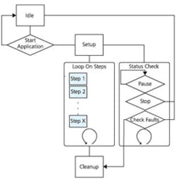
Figure 3. Application Flow Chart
- Setup: Defines and initializes the test setup parameters such as nulling sensors or creating actuator home positions.
- Main: Determines what test steps are to be executed and how many times they are to be looped or repeated in a life-test cycle. A step is defined to be a modular call to a predefined function. Each function performs a specific action with the resources, such as Get Offset, Apply and Hold pressure, and PID static control.
- Cleanup: Executes steps such as venting valves and resetting home positions.
Once all the parameters have been defined and the test script configured, the files are sent to the cRIO real-time control module. Upon receiving the files, the control module will start the script. A diagram of the flow is seen in Figure 3.
Concurrent to the setup, main, and cleanup steps, the application will monitor the alarm faults, stop button, and pause button. This ensures the safety of the system by continuously monitoring sensors. At any time, if a safety sensor exceeds its predefined limit, the system will shut down properly.
The PC host application monitors data from the module. The data from the instruments and sensors can be graphed against time or against another channel. As a result, load vs. displacement can be properly measured. All the data also can be logged to a text file for future analysis. In addition, the PC application provides an interface which can be used to manually control the resources to develop the required steps to perform a test.
Example Test Configuration
A typical test sequence for Recaro might be a seatback life test sequence. Through the channel configuration tools, the technician would define the name and resource for each pressure/load cylinder, photocell sensor, and electronic actuator. Also, the technician would assign a custom linear scale for each measurement.
For example, a pressure sensor returns a voltage from 0 to 5 V. A scale is used to convert this measurement into engineering units such as psi. Through the script interface, technicians would set the home position, enter the number of cycle counts, and define any dwell times and the desired range of motion. The test then would run continuously until either it finished, failed a step limit, or stopped due to a triggered alarm condition.
If the system stops for any reason, the technician has the option to continue the test from the previous cycle count. This is helpful because if the test stops for a minor issue that is subsequently corrected, then the test can continue on the same UUT and complete the number of cycles required if the change didn’t affect the integrity of the test.
Test screens also are provided to simulate a test before applying the script to the full cycle routine.
Conclusion
The test system developed by G Systems has allowed Recaro to complete aircraft seat life tests more rapidly, more economically, and with improved test reliability. Previous to implementing this new test platform, all tests had to be outsourced to an independent test lab which was time-consuming and expensive.
Recaro now runs testing in-house, providing engineering and design departments with faster engineering feedback and a much more cost-effective test solution. Tests can be performed reliably for weeks at a time, and then the platforms can be quickly reconfigured for different seat models. G Systems’ configurable software allows each station to run multiple test routines on multiple seat models, all controlled through a GUI designed to maximize test station flexibility.
About the Authors
Mike Taylor is a project engineer at G Systems. Before joining the company in 2009, he held positions as a test engineer with Delphi Product & Services, application engineer at National Instruments, and research assistant at Lynntech. Mr. Taylor received a B.S. in mechanical engineering from Texas A&M University. e-mail: [email protected]
Andrew Kahn has been G Systems’ marketing manager since 2005. Previous experience included positions as adjunct professor, University of Dallas, Graduate School of Management; director of marketing at Optek Technology; and manager of business planning, D/FW International Airport. Mr. Kahn graduated from Wake Forest University with a B.A. in chemistry and Carnegie-Mellon University with an M.B.A. e-mail: [email protected]
G Systems, 1240 E. Campbell Rd., Suite 100, Richardson, TX 75081, 972-234-6000.
About the Author
Comment About the Article
To join the conversation, and become an exclusive member of Electronic Design, create an account today!

Leaders relevant to this article: