Complexities of Marine Lightning Protection, Part 2

Part 1 of this article appeared in the April issue of EE
Most boats and ships usually ride out a thunderstorm and the high winds, tornados, hail, and floods it can produce. But the ESD event called lightning that it creates is a very different situation. Lightning can be extremely hazardous, particularly to a boat’s structure, electrical and electronic equipment, and crew.
When far from shore, there is no safe haven when a storm and accompanying lightning occur. As a result, lightning protection must be addressed, and the effective method is a lightning protection system (LPS), a designated intentional low-impedance path for the lightning current to take to earth should a lightning leader come within striking distance of the LPS.
An LPS is a bonding, grounding, and shielding configuration made of four distinct parts: air terminals and down conductors discussed in Part 1 and a low-impedance ground system and flash-over protection.
Earth Terminal
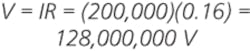
Cloud-to-ground lightning finds its way to earth, and there is absolutely no way to stop it. Fortunately, sea water is a good conductor. Right at the earth terminal where the 200-kA lightning surge connects to the sea water, the terminal voltage for a resistance (R) of 0.16 ? would be

Unfortunately, if the earth terminal were submerged in a nonflowing fresh water lake, where R = 640 ?, the terminal voltage would be
Even with a 20-kA strike (the 50% strike value), the terminal voltage would be 12,800,000 V, and this doesn’t include the inductive effects. At 3-MV per meter, this is sufficient to break down 4 meters (13 feet) of air and why it is difficult to provide lightning protection for small boats used in fresh water. The conclusion: Don’t sail in fresh water during thunderstorms!
As the negative or positive leader tip approaches, the opposite charge at the earth’s surface intensifies. So, when lightning makes contact with the homogeneous conducting surface, the greatest excess charge current flows radially away from the current injection point.
This happens because excess electrons or protons from the stroke repel each other, the opposite charges in the surface attract these charges, and a radial path in the surface of the conductor allows this to happen with the lowest energy. A spreading distribution rapidly increases the contact surface area, lowering the resistance and inductance and allowing the discharge to dissipate as quickly as possible.
Observations of triggered lightning by The Aerospace Corporation indicate the spreading radius with surface arcing is approximately 18 meters (60 feet), and the current has an approximate 15% downward penetration at the injection point. Since the distances are large with respect to a 10-m x 3-m fiberglass reinforced plastic (FRP) boat, the best that can be done with the least amount of conducting material is to put long metal strips fore to aft on the bottom of the hull and hope that the charge does not arc through the side of the hull. This is a possibility if the down conductor passes through the center of the boat and the LPS is not designed to accommodate internal lightning currents. See NFBA-780 paragraph A10.5.2.1 for more information.
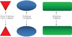
Figure 1. Breakdown Voltage of Air at Atmospheric Pressure
The EF strength required to launch a streamer depends on the shape of the electrode. The approximate values are shown here. Breakdown occurs first at sharp points and edges.
Side Flash Protection
The biggest problem in a small boat is a side flash, which simply is a lightning-stroke detour from a conductor through air to another conductor or to earth. Ordinarily, air is an insulator, but with a high enough electric field (EF), air becomes conductive. That’s how the stroke gets from the cloud to ground.
The EF strength needed for arc-over depends on voltage, spacing, and shape. For example, breakdown EF between conductive points is approximately 10 kV/cm, curved surfaces 15 kV/cm, and flat surfaces 30 kV/cm as illustrated in Figure 1. Side flashes are caused by large potential differences. The magnitude determines the distance. The lightning path is unpredictable, and to prevent side flashes, all conductors within the flash-over region must be bonded together to minimize potential differences.
Lightning currents follow the lowest impedance path to earth, and they typically don’t flash-over from an established path to a higher impedance ungrounded path. Nevertheless, crew members are a lot more conductive than air. Lightning on an ungrounded path may flash to a grounded crew member or through an ungrounded crew member located between the ungrounded lightning path and ground. Don’t move around during the storm!
LPSs should be located outside of the protected structures to prevent side flashes to interior objects and people. The structure, which may be metal or a dielectric, acts as a shielded enclosure. For this reason, a metal car is a reasonably safe place to be in a thunderstorm because lightning stays on the outside surfaces. The windows must be closed for it to be safe since the dielectric breakdown voltage of wet air is less than that of wet glass, so lightning will ionize the air on its way to earth and flash around the outside surfaces rather than pass through the glass. The glass acts as a dielectric shield.
The same principles apply to an FRP boat hull if the lightning currents are kept outside. This is difficult to do in a sailboat because of the location of the mast and its associated guying.
Often, the mast and the stays are brought through the deck and fastened within the cabin area. Even with a deck stepped mast, there always are metallic penetrations through the dielectric and often a metal compression post between the keel and deck. Any down conductors that must pass through the cabin area should be as straight as possible with a bend radii >8 inches and run through a dielectric shield to minimize corona formation and side flashes.
One approach is to run the insulated down conductor through PVC pipe. PVC has a dielectric breakdown strength of approximately 1,100 V/mil. The breakdown for 1-inch diameter schedule 40 pipe with a wall thickness of 133 mils is approximately 140,000 V while schedule 80 at 179 mils is 197,000 V.
Shielding
Shielding isolates the lightning energy from the crew, components, and materials that may be injured or damaged by the side flashes. Shielding may be metal, which is preferred because it also reduces the radiated EF and HF components, or a dielectric such as plastic or glass.
The breakdown voltage is determined by the dielectric thickness. If the EF is high enough, any material will ionize and become a conductor. For example, air has a dielectric strength of approximately 3 MV/m which is 75 V/mil. FRP is approximately 500 V/mil. Accordingly, air is 6.5 times more likely to breakdown than FRP. Glass is approximately 300 V/mil.
When breakdown occurs, bound electrons are freed within nanoseconds, and the material becomes a conductor with major structural damage. A little fiberglass won’t protect the boat. If no grounded paths exist, lightning will blow a hole(s) through the hull to get to earth.
The biggest problems are metallic fasteners screwed or bolted through the dielectric shield to attach blocks, winches, stanchions, or chainplates. The differences in conductivity between the dielectric and the metallic fasteners such as screws, bolts, and rivets cause streamers to form at the fasteners and lightning leaders to be attracted to the metal.
Lightning current can pass through the dielectric by way of the fasteners. It’s especially bad for those penetrations that also may act as down conductors such as masts, shrouds, and stays. The diameter of the larger fasteners is not much different than that of the actual lightning channel.
Lightning currents that penetrate the dielectric shield enter into the interior below deck where they can arc to other metal surfaces within the hull and cause severe damage and injury. To eliminate this threat, it would be necessary to provide some means of preventing or minimizing lightning strike attachment to the fasteners. In some cases, this can be done by using fiberglass or nylon fasteners, but plastic fasteners generally are not strong enough to handle the dynamic loads found on a boat, especially for sail handling.
One approach tried in aerospace applications was to cover the exposed fasteners with a dielectric film. This did not prove to be very satisfactory. Dielectric materials do not have to have metal penetrations to be a problem. They are transparent to the electric and magnetic fields, so the extremely high EF’s exterior to the dielectric can initiate streamers from metal components within the structure. The streamer characteristics and subsequent attachment points are determined by the thickness of the dielectric or by any defects in or penetrations through the dielectric materials.
Although uniform homogenous fiberglass/FRP has good dielectric strength, the fiberglass cloth, woven roving, and mat have microscopic holes formed by the overlay of the weave, plus the thickness varies to handle load conditions. As a result, there will be localized areas within the material where the dielectric strength is significantly different. Given enough energy, most dielectric materials suffer breakdown and catastrophic failure.
Additional Considerations
There are several more items that need to be mentioned for better awareness of the protection problem:
- The marine environment is highly corrosive so all LPS materials should be both conductive and corrosion resistive. The recommendations are copper, bronze, monel, and stainless steel.
- The engine often is grounded through the drive shaft and propeller. It should be directly connected to the earth terminal (grounding plate) in a manner that keeps lightning current from flowing through the engine bearings.
- Minimum requirements for a lightning grounding plate are 0.09 m2 (1 ft2) surface area, 5 mm (3/16 in.) thickness, and 19 mm (3/4 in.) width.
- The radio antenna may serve as a lightning protective mast if it is capable of handling the lightning current. In general, the antenna is sacrificial, so carry a spare.
- Disconnect communications/radio equipment from the antenna prior to any lightning activity.
- Gas gaps and lightning/surge protection devices must be used to protect electronic equipment.
This article doesn’t cover everything, and it is not meant to be a design guide. It was written to emphasize the difficulty in providing lightning protection for equipment and crew on FRP boats with lengths from approximately 6 to 30 meters (20 to 120 feet), especially the smaller craft. The prominent standard used for lightning protection design is NFPA-780 (2011): Standard for the Installation of Lightning Protection Systems.
About the Author
Ron Brewer is a senior EMC/RF engineering analyst with Analex at the NASA Kennedy Space Center. The NARTE-certified EMC/ESD engineer has worked full-time in the EMC field for more than 30 years. Mr. Brewer was named Distinguished Lecturer by the IEEE EMC Society and has taught more than 385 EMC technical short courses in 29 countries and published numerous papers on EMC/ESD and shielding design. He completed undergraduate and graduate work in engineering science and physics at the University of Michigan. e-mail: [email protected]
FOR MORE INFORMATION
About the Author
Comment About the Article
To join the conversation, and become an exclusive member of Electronic Design, create an account today!

Leaders relevant to this article: