Simulating Tough Challenges With PXI
No one will be surprised when we say that technology is becoming ever more pervasive. There are new applications announced daily and many more already in our cars, PCs, appliances, and home theaters that did not exist several years ago. Every year, products and systems with more intelligence and operational convenience are available and usually at a lower cost than previous models.
The basic premise of our market-driven economy is the need to create new products that people will purchase. Essentially, technology drives the economy of this and many other developed nations.
But just as technology progresses, test technologies and their implementation strategies must change as well. The testing requirements nowadays include factors such as simulation of sensors, fault insertion, higher data rates, and increased precision. All of this must be accomplished while simultaneously improving test throughput and lowering costs. While this has always been a tough challenge for our industry, it seems to be a more daunting prospect to support today’s technology.
Fortunately, the test and measurement industry has been developing new solutions to address these needs. In many cases, the solution has been PXI, which has shown itself to be a remarkably flexible platform. Over the last 14 years, the 50-plus members of the PXI Systems Alliance (PXISA) have continued to innovate and create modules that can address the newest technologies. Actually, unique test solutions are being developed in PXI that are not available in other platforms.
Why PXI?
Some of the reasons for PXI’s success are obvious. Many vendors, many more products, and lots of previous application successes are key reasons. But looking beyond this, there are other reasons for success:
- Choices in Software: Many programming languages including real-time operating systems (RTOS) and focused software for applications like hardware-in-the-loop simulation (HILS) make implementing PXI easier.
- Connectivity: The best hardware is useless unless you can connect it to the UUT. Fortunately, there are vendors who have created mass interconnects that work well with PXI.
- Vendor Creativity: The small size of 3U was seen as a detriment back in 1997 when the specification was released. It was felt that the small size, especially when compared to VXI, would limit the bandwidth and density that could be achieved. Fortunately, the naysayers were wrong. Switching densities of 4,000 to 8,000 relays in a single matrix, 1,000-V isolation, and RF instrumentation of 6 GHz and greater are just a few examples of what is possible in PXI.
- Capability to Work With Other Test Platforms: In many instances, hybrid test systems are the norm. This can be for reasons like availability of test equipment, test budgets forcing hardware reuse, and partial rehosting/upgrades of existing test systems. PXI has been shown to work well in these environments.
- System Integrators: This segment of the test industry has embraced the PXI platform as a solution for many applications. Their ability to make PXI work is a big part of the success.
But enough talk on the why. Let’s focus on the how. Because we cannot adequately present applications on every PXI advantage, we are going to focus on those where specialized simulation of a UUT’s operating environment is necessary for test. Granted, every test system is a simulator as the system replicates the car, PC, or missile the UUT will ultimately end up in. But new applications require new simulation techniques, which is what we want to showcase.
Automotive ECU Fault Insertion
Customer: A leading French systems integrator that develops functional and design validation testers for the automotive and aerospace industries.
Application: The end user required test systems to validate the design reliability of its engine control units (ECUs), also known as power-train control modules (PCMs) or engine control modules (ECMs).
The systems integrator was tasked to find a more flexible and cost-effective alternative to proprietary HILS solutions. The existing system was an internally developed design and used a manual method of performing fault simulation. To insert a fault, the operator had to move cables on a patch panel to short pins together, force a stuck-at Vbat or Ground, or inject false sensor data. This method was slow, subject to human error, and expensive. Given the issue of liability when electronic systems fail and the continuous pressure to lower costs, a strategy change clearly was necessary.
Fault simulation during the design and validation of ECUs is a method of establishing solid predictions for reliability and firmware verification, ultimately ensuring the safety of driver and passengers. An ECU relies on information from a set of sensors and controls to decide what to do with the device it is managing. These sensors are themselves often working in extremely hostile environments, and predictably, failures can occur in the sensors or their interconnections. The ECU has to respond appropriately to these component failures as well as to genuine system faults.
The idea of testing for system failures is not new. It is an important aspect of ECU validation and involves the introduction of electrical faults into a system. The test process typically duplicates various conditions which could occur because of corrosion, short/open circuits, and other electrical failures inherited through infant mortality, age, damage, or even faulty installation.
Solution: PXI provides an open platform for HILS requirements. Combining this with the large range of hardware available from Pickering Interfaces and many other vendors enables the most flexible and cost-effective alternatives to proprietary systems. The modularity and openness of PXI enabled the integrator to design a highly scalable solution with plenty of potential for evolution.
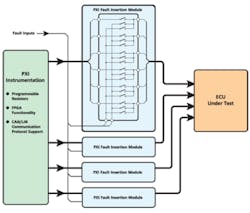
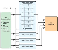
There is a wide range of fault insertion switching modules in PXI specifically designed to assist the simulation of fault conditions in automotive and avionics applications that involve the reliability testing of safety critical controllers. If you look at the block diagram, you can see how fault insertion modules work in this test strategy. These switching modules are designed to route various fault conditions between a test fixture and the UUT. Faults include open circuit, short circuit between UUT connections, and short circuits to other signals such as power, ignition, and ground. Serial bus faults can be injected into the circuit as well.
Other fault simulation systems also are available commercially. However, they tend to be proprietary, do not work as well with other vendors’ products, and can be very expensive.
In addition, every vendor providing PXI products must offer software driver support for RTOS, a key requirement in HILS. The reason for RTOS is the deterministic nature of the test: Responses by the UUT, especially in the areas of active safety, need to be presented at exact times to protect the vehicle’s passengers.
The solution was accommodated in four 3U PXI chassis. Modular products from Pickering Interfaces included 24 modules to route fault insertion signals (one module with 30-A switching, 22 modules at 20 A, and one module at 2 A) plus programmable resistor cards for sensor simulation.
As PXI is an open platform, modules from other vendors also were included for FPGA functionality and CAN/LIN communications protocol support. In addition to the cost/flexibility advantages, the application of PXI solutions also improved test-system performance and cabling elegance in comparison to the original proprietary system.
Satellite Payload Testing
Customer: A leading small satellite company delivering operational space missions for a range of applications including Earth observation, science, and communications. The company designs, manufactures, and operates high-performance satellites and ground systems for a fraction of the price normally associated with space missions.
These cost savings are achieved by implementing commercial off-the-shelf (COTS) satellite technology. This process adapts standard consumer technologies, such as those used in PCs, to the unique environment of space.
Application: Satellite payload testing is critical for several reasons. First, as the hardware is extremely expensive, a lot of testing is expected. Second, if a failure occurs after launch, it is extremely difficult, but not impossible, to return the entire product for service!
Satellites and payloads are complex systems made up from multiple mixed-technology subsystems. The traditional approach to satellite development is very linear: specify everything up front, design to specification, test the prototype, then assemble and verify the flight unit. This linear approach obviously is very time-consuming and unsuitable for rapid, lower cost developments that require more agile methodologies.
The use of simulation can provide major improvements on cost and time scale. Using COTS components and standard toolsets, a subsystem simulator can be developed and tested far in advance of flight-grade equipment, often at a much lower cost. This yields two major advantages to the project:
- The designs are developed and progressed far in advance of the main development. This allows very early detection and resolution of inherent design issues, avoiding any costly rework of flight equipment.
- Interface simulators can be used for system integration testing far in advance to identify and resolve subsystem integration issues. This is especially important on large-scale programs where a single satellite may have parts made by a dozen different subcontracted manufacturers. Unlike hardware, the simulator is open, providing a much higher degree of debugging capability.
Solution: When specifying hardware for this latest simulation requirement, the customer chose not to base it on heritage tools and strategies. Instead, it was decided to take a fresh look at what was available and what was possible, with the goal of selecting an optimally engineered solution within a defined budget.
The decision was made to base the hardware primarily upon the PXI standard, with Pickering Interfaces as one of the main suppliers. The reasoning behind this decision came down to one statement from the customer: “The solution fitted our requirement as opposed to our requirement having to fit the solution.”
In the case of the thermal control system that monitors key temperatures within the satellite, a PXI high-density precision resistor module was needed. Six modules were used to simulate 36 space-grade thermistors across the range of -80°C to +55°C. These PXI precision resistor modules constituted the only commercially available solution that could cover the entire range of the thermistors requiring simulation.
In addition to the precision resistor modules, Pickering Interfaces also supplied switch cards for both signal and high-power switching, isolated power supply cards, and MIL-STD-1553 bus analyzer modules. The main functions of the switching modules were to physically isolate interface paths, simulate RF switch feedback contacts, and distribute load channels across multiple paths.
The modules provide complete and physical isolation from the DUT where necessary. This is a key requirement when connecting into flight-grade equipment, whereby a single-point failure in the test equipment can easily cost more than $1.6 M in flight hardware.
Diesel Engine Temperature Simulation
Customer: A world market leader for large diesel engines whose products are used in ships and power stations. Some of these diesel engines are being manufactured for a new class of container ships that is among the world’s largest cargo carriers.
Application: The controllers for the massive diesel engines in ocean-going vessels require many temperature sensors to determine whether the engine is operating correctly. This is primarily because of the sheer size of the engine block, which means that many sensors are required to ensure that the engine operates in the correct temperature range and that hot spots are identified quickly. It would be difficult to have an engine block available for system test, not to mention the time it would take for the engine to reach operating temperature. Sensor simulation provides a cost-effective means of testing the controller without having an engine on hand.
This requirement involved the support of ECU development for 40,000-kW ship diesel engines. In terms of horsepower, 40,000 kW equates to approximately 55,000 hp!
Besides other ECU tasks, there was a requirement to simultaneously simulate 144 channels of PT100 temperature sensors. These sensors are RTDs as opposed to thermocouples. The temperature range in this requirement was -20°C to +250°C with an equivalent resistance range of 92.160342 ? to 194.074250 ?. Extreme precision also was required, demanding accuracies within 0.11°C at -20°C (equivalent resistance deviation within 43 m?) and 0.65°C at 250°C (equivalent resistance deviation within 220 m?).
The customer’s original method of sensor simulation was achieved manually. This comprised 288 precision potentiometers covering both coarse and fine adjustment along with 144 switches for short circuits and an additional 144 switches for open circuits in the simulation of faulty wiring connections to the sensors. All of these components were adjusted and controlled by hand. The need for automation was obvious to save time and improve performance and repeatability.
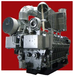
Courtesy of MAN Diesel & Turbo
Solution: With various measurement and stimulus modules already available in PXI and a requirement to support RTOS software, PXI was seen as the natural choice of platform for new product design.
The solution developed was a 3U PXI module that supports either six channels of RTD simulation in one slot or 18 channels in two slots. Based upon existing design principles, the module provides a setting resolution of 2 m? and a resistance accuracy of better than 0.1% on all channels. Each simulation channel can offer a short or open circuit setting to simulate faulty wiring connections to a sensor. Furthermore, the calibration or verification of each resistor channel is possible by connecting the module calibration port to a high-performance DMM. The use of simple resistance value calls makes programming simple, using an application programming interface (API) to convert a temperature request to a resistance request through a model of the sensor used in the real engine.
The end product enabled a cost-effective method of simulating either PT100 or PT1000 RTDs with very high accuracy. Eight modules achieved the 144 channels of PT100 required in this application, accommodated in 16 slots of 3U PXI chassis space.
A Simulated Conclusion
From these three applications, it’s clear that PXI products can simulate the signals necessary for a variety of applications, including consumer, transportation, and aerospace. PXI can achieve the densities required to make the system manageable on the test floor, be accurate enough to meet customer demands, and support specialized environments like RTOS.
About the Authors
Shaun Fuller is the switching product manager for Pickering Interfaces and based at the company headquarters in Clacton-on-Sea, England. Over the last 20 years, he has held engineering and product management positions within the company. [email protected]
Bob Stasonis is the Americas/Asia sales and marketing director for Pickering Interfaces. In the last 30 years, Mr. Stasonis has held technical, sales, and marketing positions with Pickering Interfaces, Teradyne, GenRad, and Schlumberger. He is on the board of directors and past president of the PXISA, a board member for the LXI Consortium, and the vice president for the American Society of Test Engineers. [email protected]
About the Author
Comment About the Article
To join the conversation, and become an exclusive member of Electronic Design, create an account today!

Leaders relevant to this article: