Ensuring Well-Connected Applications

Courtesy of DIT-MCO
Before you buy a cable tester, you need to decide what it should achieve. At the lowest level, a tester identifies shorts and opens resulting from mistakes made when the cable was fabricated or caused by damage to the individual wires or connector pins.
Modern wiring harnesses often include resistors, capacitors, relays, lamps, and perhaps motors and sensors. For a complete test, these things also must be addressed in addition to the wires. Some cable testers handle several types of components but may require an auxiliary power supply. Optionally available LCR meters measure inductance, capacitance, and resistance to supplement the tester’s basic voltage and current capabilities.
Beyond continuity testing, which verifies that only the correct connections exist, high-voltage insulation resistance (IR) and dielectric withstand tests also are specified by many wiring standards. These tests relate to safety as well as long-term operation. Where continuity testing typically uses voltages up to 30 V, these high-voltage tests often are performed at 1,500 VDC (1,060 VAC). Specialized testers support hipot up to 5,000 V and understandably emphasize operator safety.
When a tester is used as a construction aid during cable assembly, correct routing and connector termination can be automatically verified wire by wire. The actual assembly job may be assisted by operator prompts in the form of on-screen graphics, synthetic speech instructions, or LED-highlighted connector cavities.
Further, multiple levels of security are available to ensure that only authorized personnel alter the test program. It’s even possible to have the test program actuate clamps to prevent cable removal before test completion and sound an alarm if this is attempted.
Specifications of testers with these and other capabilities are listed in the comparison chart accompanying this article.

Of course, not all cables are conveniently tested on a workbench. Large test systems comprise a central controller and several remote switch units. This architecture supports extensive cable harness testing on aircraft having thousands of widely distributed individual circuits. Relatively short adapter cables attach the remote units to the aircraft connectors, and separate communications cables connect the remote units to the central controller.
A very practical addition to a large test system is suitable cable support hardware. High-current conductors and multiway cables are heavy. It’s necessary to provision adequate mechanical stanchions, loops, straps, and related fasteners to avoid straining the adapter cable connectors or damaging the cables themselves.
Continuity Testing
Typically, lower and upper thresholds are chosen that define a short and an open. In the lowest cost testers, these may have the same value such as 1 k?, a short being less than 1 k? and an open being more. CAMI Research’s Christopher Strangio, director of marketing, provided an example of a cable used to control a motor. In this case, the manufacturer set 0.8 ? as the upper test limit for conduction and 10 M? as the lower limit for isolation.
Very low resistances can be measured by the Kelvin 4-wire technique. Cirris Systems offers this feature in the Easy Touch Tester that measures resistance as low as 1 m?. The same tester lists 0.1 ? as the lowest 2-wire resistance measurement.
There is a practical upper limit to 4-wire operation. DIT-MCO’s Model 2135 Tester reverts to 2-wire measurements above 10 ? and QuadTech’s Meridian Wire and Harness Analyzer above 400 ?.
DIT-MCO has developed a compensated continuity resistance mode of operation. It generates and stores tare resistance tables that later serve as reference values to be subtracted from the overall resistance of a circuit. Providing adapter cables with 4-wire-ohms capability is expensive for the very large distributed test applications that DIT-MCO machines address. Subtracting the series resistance of the test connectors and adapter cable from the overall resistance is a cost-effective alternative.
Making the Connections
Plug In Anywhere
An innovation that simplifies very large test setups is the random connection feature found on some testers. Both DIT-MCO and CK Technologies (CKT) offer this capability. Each adapter cable has built-in identification that the tester software recognizes regardless of where the cable is plugged in. The test routine’s sequence of logical inputs/outputs is never changed, but it’s mapped to the correct set of physical connections to match the way the adapter cables have been connected.
To handle very large pin-counts and DUTs with physically distant harness test points, distributed hierarchical tester architectures have evolved. Typically, tests are controlled from a central chassis. Connections to adapter cables may be accomplished via separate remote switching chassis that communicate with the central controller.
Several forms of switching chassis are available to suit the application. The CKT-1175, for example, offers suitcase-size chassis, rack-mounted roll-around chassis, and chassis configured as line replaceable units (LRUs) compatible with ARINC 400/600 Series form-factor specifications. This means that the switching units can directly replace an aircraft’s LRUs, eliminating most if not all adapter cables.
Some testers have universal connectors on the main chassis. Cablescan calls it a universal interface system. The module has three rows of spring-loaded pins arranged on 0.156″ x 0.156″ centers. Universal adapters are available with 12, 18, 24, 30, 36, 42, 48, 54, and 60 pins wired to connectors that mate with your DUT cable’s connectors.
Another type of universal interface comprises two parallel multiposition connectors spaced a few inches apart. Adapter boards with pins protruding from the back plug into the connectors. Because each pair of pins connects to a separate switch channel, all the pin-pairs are electrically equivalent. The adapter boards are the width required to accommodate the number of DUT connector wires.
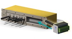
Figure 1. Partially Loaded Connector Panel; Close-Up View of a ZIF Adapter Cable Connector (inset)
Courtesy of CKT
CKT has developed a zero insertion force (ZIF) adapter cable connector system (Figure 1). The adapters have whatever width is necessary to accommodate a DUT connector’s circuits and, because of the tester’s random connection feature, plug into any position on the connector panel.
Smaller Systems
CAMI Research’s CableEye® Test System is a good example of a small tester intended for use with loose cables. Expansion modules and at least 18 types of adapter boards are available. The unit scans 128 points for opens, shorts, and miswires and provides a full-color diagram of the cable being tested on the control PC. The CableEye HVX System is a high-voltage version that adds IR and dielectric breakdown test capabilities to 1,500 VDC.
Many of the testers from Cirris Systems, Cablescan, and Dynalab Test Systems also have capacities of 1,000 pins or less although a few larger models are available. Each company has its strengths, but they agree that ease of use and flexibility are key capabilities.
Brent Stringham, director sales/marketing at Cirris Systems, said, “Customers are looking for cost-effective solutions that are easy to use, easy to adapt to, and offer quick changeover flexibility. Another growing need is for the tester to provide statistical test data for all assemblies tested. This not only must include pass/fail data, but also specific error details and, in many instances, actual measured values even on good cables.”
Dynalab’s Eric Harter, product manager, explained that although the NX Wire Harness Tester supports stand-alone operation, the company also offers a PC application called NX View. “In addition to the normal error and status messages, NX View provides images of the connectors, clearly showing the operator which connectors and cavities are associated with the displayed error,” he said. “On the same screen, NX View can display instructional information that originates from a variety of sources: documentation files, graphics files, movie files—anything that can be displayed in a web browser.”
Backplanes
Backplane testing is a specialized application of a cable tester that highlights the importance of the physical interface to the DUT. WEETECH and Testpro specifically address this market. Several other companies provide electrically equivalent equipment but generally with less efficient interfaces.
Testpro’s Model TP2101 is a generic designation that includes all custom variants based on the same architecture. In operation, the backplane DUT is positioned at the rear of the test fixture. The tester switch cards plug into separate in-line adapter modules. The fixture is designed to directly insert all the adapters into the backplane connectors as a group. This is accomplished with the help of pneumatics or a lever arrangement that provides the necessary mechanical advantage.
WEETECH has taken a different approach, as Chuck Anderson, the company’s sales and service manager, explained: “We have developed a system that uses an external transistor-based matrix. This brings the test points in direct contact with the backplane under test and eliminates test-point adaptation cables. The only cable between the system and the test points is a single control/measurement cable daisy-chained to each test card.”
Refinements
High Voltage
Both IR testing and dielectric strength testing stress a cable’s insulation to expose faults or degradation that could lead to a fault. The capacitance between the wire being tested and ground must be considered when applying a large DC voltage.
Most high-voltage testers offer programmable rise and fall times that limit the inrush current when the voltage is applied. Typically, no breakdown should occur within some period of time, so the time during which the high voltage is maintained also is programmable.
Sefelec’s Synor 5000P High-Voltage Cable Tester is a good example of a tester with continuity, IR, and dielectric strength capabilities. The product datasheet refers to IR testing as quality verification often required in aerospace or military applications. Dielectric strength tests increase the insulation stress to accelerate incipient insulation breakdown. Arc definition, detection, and measurement are involved in this type of test.
The tester is configured via a range of switching cards with upper voltage limits from 350 VAC to 6,000 VDC. Because of the large insulation distances needed at very high voltages, the number of channels per card is 128 at low voltage and only 16 at the highest levels.
Software
Over time, a large number of cable designs will be produced by a company, and each will have at least one test routine associated with it. Also, a tester’s capabilities that initially were adequate may be found lacking as more complex harnesses are developed. If a new tester is required, the large investment in existing test routines must be preserved.
This is where test-routine translation programs become important. Dynalab’s Mr. Harter explained, “Many of our customers have asked us to provide means of importing data from datasets generated by their design and production control systems. As a result, we have a variety of source file formats that can be directly imported into our NX Editor software. This level of flexibility in data importation formats extends to how our customers encode part number differentiation.”
Dynalab’s NX Tester is used in industries where products may have several options that change the harness details. An extended version of the NX Editor supports conditional compilation: A special test program is generated comprising those tests needed to match the options fitted. This is done dynamically as each harness is presented for testing.
Some testers generate their own test program based on a golden cable. The technique has been used in bare-board PCB testing for more than 30 years. However, component auto-learn is a significant improvement. Not only does the tester generate its own wiring tests but it also determines the types and values of components attached to the cable. This feature is available in QuadTech’s Meridian Wire and Harness Analyzer.
Test system optimization is another area to which software has been applied. CKT’s Vice President for Product and Test Strategy Development David Shier commented, “TSLArchitect is a software tool that virtually instantly optimizes the system size, cable lengths, and switching distribution given the UUT connector sizes and locations. A 3-D representation of the switching locations and UUT connector hookup allows the engineer to rotate the view to verify the design prior to committing to the hardware.”
DIT-MCO’s TestExecutive Touch is an interesting adaptation of a wireless hand-held pocket computer for remote wiring harness test execution. In a large distributed test setup, manual controls may need to be set to various positions during a test or the operation of an actuator observed and verified. TestExecutive Touch allows a technician to move around, under, and inside the UUT and control the tests via a Wi-Fi connection.
Addressing Your Application
As shown in the comparison chart, a wide range of cable testers is available. In addition to cost, the key specifications differentiating one from another include number of wires, test speed, continuity voltage and current ranges, high-voltage capability, and additional special features. However, there are other less obvious characteristics that may make one tester better suited to an application than another.
For example, the large test systems from DIT-MCO and CKT are built with electromechanical relays rather than reed relays. Reed relays are smaller and tend to have lower power ratings that may be fine in your application. If you don’t need a 1-A or 2-A test current, reed relays can operate for a very long time, and many are found in test instruments and ATE. On the other hand, in a large test system used on multimillion dollar UUTs, the increased ruggedness of electromechanical relay contacts makes a difference.
About the Author
Comment About the Article
To join the conversation, and become an exclusive member of Electronic Design, create an account today!

Leaders relevant to this article: