Runtime-Defined Instruments Tackle Modern Bus Designs
Defense and aerospace assemblies designed over the past decade introduce digital bus test requirements that demand a new approach to ATE instrumentation. There are three key issues surrounding the test of buses used at all levels of assembly from multichip modules and PCBs through line-replaceable modules and boxes:
- The speed of the buses that exceeds the 50-MHz to 100-MHz limit of most traditional digital test units.
- The wide variety of buses used in these recent designs.
- The real-time interaction between the test equipment and the UUT that is becoming increasingly important to emulate the end environment.
The Emerging High-Speed Bus Problem
The speed of digital buses is a primary factor driving the need for new test equipment. In the past, digital test units focused on meeting the physical requirements of various standard logic families such as TTL and CMOS with relatively large voltage swings and the need for significant tester drive current capability. Flexible, programmable ATE pin electronics, by necessity, dissipated very large amounts of power.
Addressing the wide variety of products built with these technologies, test equipment has become very flexible in terms of highly programmable voltage and current levels as well as flexible timing capabilities. The limitations of these device technologies and the associated UUT generally have been satisfied with data rates that topped out in the 50-MHz region.
More recent designs first moved to lower voltages with single-ended logic and families such as LVTTL. To drive longer distances and attain data rates above 100 MHz, the use of differential logic, LVDS in particular, has become almost ubiquitous. Lower voltages and current-mode logic result in far lower power requirements for ATE. For newly designed products, ATE must focus on the requirements that accompany ever-increasing speeds and new device technologies.
The fundamental nature of bus organization is rapidly evolving. Custom parallel buses are becoming narrower and faster, ultimately to be displaced by standardized multigigabit serial buses. The past decade has seen a combination of fully custom bus designs as well as various attempts at standardization. Fast serial buses require industry standards and the associated silicon support. As a result, the long-term trend is for future designs to rely nearly exclusively on strict bus standards.
Ultimately, new designs may focus on a small number of standardized approaches and could potentially narrow the bus-type diversity. Despite these trends, the defense and aerospace equipment pipeline is long and filled with many design generations. For the next 20 or more years, ATE will see a complex mix of high-speed bus characteristics—a wide range of speeds, parallel and serial, standard and custom. Test departments must cope with dozens of widely divergent bus types rather than a few highly standardized.
Traditional ATE test programs typically act as automated test scripts: They execute a sequence of stimulus and measurement operations using discrete analog and digital instrumentation under computer control. This procedural approach has worked well in the past for automating tests that otherwise would be executed manually on a test bench, providing improved throughput and repeatability.
Newer products require more realistic simulation of the native UUT operating environment. In particular, the test equipment may need to rapidly react to complex data received from the UUT. High-speed data analysis may be necessary to provide acceptable test times when faced with huge quantities of data.
The quantity and bandwidth of raw stimulus and response data may make it impractical to store to disk. Real-time processing can calculate stimulus values and make UUT quality assessments on the fly.
Real-time analysis and calculations also may be required to provide immediate feedback to another UUT bus instrument as part of closed-loop system emulation, such as executing an operational flight program (OFP). An OFP in an aircraft depends on the actual surrounding avionics during execution. In a test OFP, the ATE must mimic the functionality of the surroundings. These test requirements exceed the capability of both the test equipment and the automation procedures of the past.
High-Speed Digital Bus Capabilities
An emerging class of instrumentation and subsystems directly addresses these new requirements. One UUT may feature multiple diverse, concurrently operating buses. Each bus requires instrumentation that accommodates the speed and behavior of the associated bus protocol.
Looking at each of the wide variety of bus types with a particular solution is futile because it would result in a single system with dozens of underutilized bus instruments. The only practical alternative is to provide a new level of instrument flexibility that can handle both current and future requirements.
Runtime-defined instruments allow the test program to configure the test equipment to the individual bus requirements ranging from the physical-layer configuration to the low levels of the protocol. Providing local processing on each bus instrument permits real-time data analysis and interaction with the UUT. Multiple instruments accommodate the real-world scenario of concurrently operating buses. Streaming data from one bus instrument to another allows for true closed-loop testing that emulates the in-system behavior of the UUT such as executing a test OFP.
Three key technologies have matured over the past decade, enabling the creation of runtime-defined instruments: PC-based high-level test program set (TPS) programming, real-time processors and software, and the speed and flexibility of FPGAs. The Windows-based PC offers mature and efficient TPS development tools to do the high-level setup, control, and results processing for multiple bus instruments.
Each of several instruments equipped with a real-time processor and an open FPGA accommodates the specifics of the associated bus and protocol. Specialized multicore processors coupled with new software tools allow real-time programming, a formerly esoteric undertaking, to be tackled by a proficient C/C++ programmer. FPGA-based instruments can overwhelm the hardware capabilities of the UUT for low-level operations. The multiple bus instruments execute in parallel, properly emulating system operation. Data may flow from bus to bus using high bandwidth paths between related instruments.
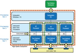
Figure 1. Three-Tier Subsystem Architecture
This three-tier processing capability allows the TPS developer to make trade-offs of performance vs. programming time (Figure 1). For example, it is easiest to implement a math function on the PC; however, the performance is much greater with the FPGA but at a higher development cost. Properly combined, this three-tier multiple-instrument approach forms the basis for accommodating each of the concurrent UUT buses, combining them into a unified subsystem, and inserting it into both existing and future test stations.
Many test activities in a high-speed subsystem can be handled using conventional high-level programming that avoids the complexity of real-time and FPGA programming. The capability to perform basic data exchanges over mature standardized buses can be delivered by the equipment provider. On the other hand, custom buses and specialized or proprietary applications require total flexibility. Accordingly, the task of programming such a facility can range from ordinary TPS development to far more complex efforts.
This increasing use of highly programmable instrumentation will place new demands on test departments. While design groups may be called upon to assist with these specialized tasks, most test groups will elect to add competence in these fields as well as draw on outside application support services.
An Approach for the Future
High-speed bus technology and the associated speed, variety of bus types, and real-time interaction will change the nature of test over the next two decades. For one test facility to tackle the wide range of resulting requirements, the instrumentation must be extremely flexible.
Runtime-defined instruments assembled into bus subsystems is a flexible solution that can meet this challenge. Providing multiple instruments, each capable of being reconfigured for a specific bus, operating concurrently and processing data in real time is the mission of this equipment.
In addition to the effect of bus requirements on the equipment is the influence it will have on test departments. Flexible real-time instrumentation will require new test development procedures and developer skills. These changes will be gradual, and test organizations need to evolve over time. Initial requirements may be met through third-party developer resources in the form of test outsourcing and consulting services.
As flexible ATE solves the digital bus test problem, the new ATE capabilities also will influence the test strategies for other test types. Mixed-signal test of baseband, RF, microwave, and electro-optical devices will combine with associated digital buses to benefit from the same flexibility and responsiveness of the digital solution. Flexible instrumentation in integrated subsystems will be the basis for bus-oriented defense and aerospace test for years to come.
About the Author
Peter Hansen is the product marketing manager for instrumentation for the mil/aero business unit of the Assembly Test Division at Teradyne. He has been employed by Teradyne since 1977 in marketing and engineering management positions. Mr. Hansen graduated from Rensselaer Polytechnic Institute in 1969. Teradyne, Assembly Test Division, 700 Riverpark Dr., NR7001-2, North Reading, MA 01864, 617-967-0017, [email protected]


