Kelvin-Ready Technology Simplifies Test Optimization
A Kelvin contacting system commonly is used on devices that require precise measurements such as power management devices, precision op amps, and high bit-count ADCs or DACs. Because most Kelvin solutions have higher acquisition costs, they are only used when other test methods are not appropriate. In fact, many Kelvin test systems also can be less reliable and require a more difficult load board layout. However, Kelvin-ready technology overcomes these obstacles through its highly configurable, optimized design.
In developing a Kelvin-ready contacting system, the goal was to design a robust system that improved on existing Kelvin test sockets or contactors. Based on industry interviews, here are the most important requirements:
- Force and sense contacts must hit device I/O.
- Load board layout does not require tight tolerances.
- Force line can handle high current.
- Can add, move, or remove Kelvin measurement capabilities easily, onsite, and for any given I/O.
- Can work for small devices and small pads and leads.
- Can use Kelvin measurements even for RF devices.
- Must be standardized and cost-effective system.
- Must have reduced maintenance, long contact life, and reusable housing.
- Contacts should be easy to replace.
The variances in package dimensions require that the force contact be designed to hit the center of the device pad. To ensure that the sense contact also will connect with the device pad or lead, it has two tines, one on each side of the force contact tip. By keeping the force contact a solid one-piece design, it can have reliable low resistance and handle greater current with than multipiece contacts. Monte Carlo analysis of the design, including the manufacturing tolerances, shows that the force and sense contacts do not have the potential for shorting or missing the device pad and creating an open condition.

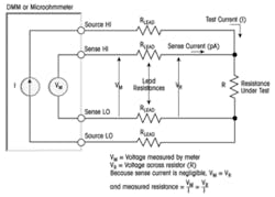
Figure 1. 4-Wire Kelvin Schematic
Source: Keithley, J.E., Low-Level Measurements, 5th Edition, pp.3-19.
The tight routing and subsequent shorting problems often associated with Kelvin solutions were addressed by using two different contact technologies. This is actually an optimized solution since the force and sense lines have different performance criteria to best measure the true parameters of the DUT. For both the non-leaded pad and leaded Kelvin-ready solutions, the gap between load board pads for the force and sense lines is greater than 5 mm, which leaves plenty of room to route signals. A 4-wire Kelvin connection schematic is shown in Figure 1.
In a Kelvin system, the sense line is monitoring the voltage at the DUT and connected to a voltmeter with a 10-MΩ to 100-MΩ input resistance so only picoamps pass through the sense contact. Any sense resistance basically has no effect on the sense measurement because it is in series with and small in comparison to the voltmeter’s resistance.
If a Kelvin measurement is not needed when using Kelvin-ready, the sense contact and the sense line load board pad can be removed for that device I/O. This allows RF or high-speed signals to be routed straight from the device to RF connectors for optimized performance. For RF testing, this also removes the stub, and the normal Kelvin-ready force contact now can test devices with frequencies above 20 GHz.
The feedback from the sense line is used by the tester’s pin electronics’ parametric measurement unit to increase or decrease the voltage at the pad or lead of the DUT. This can be very important in improving yields of RF devices where the RF output power fluctuates depending on the DC power. If the DC input power is always known at the device pad or lead, an easy setup when using Kelvin-ready, all failed devices are truly failed devices and do not require retesting.
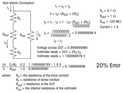
Figure 2. Measurement Accuracy Without Kelvin
Kelvin Contacting
Precision Measurement
Some devices require both RF and Kelvin testing to adequately test RF and precision analog chips within the same package. In addition, there is a focus on making devices small with larger numbers of I/Os, which in turn leads to devices with smaller pads and finer pitches.
To be reliable, a Kelvin system must ensure that the sense contact always touches the device pad, so there needs to be some built-in redundancy in the sense contact. With this, you are assured of making contact to the device pad no matter how the device is aligned in the contactor or socket.
The resulting error in measurement for the non-Kelvin case in Figure 2 is dependent on the contact resistance of the force contact. The error can be large if the device resistance is very low or if the contact resistance of the force contact is fairly high.
On the other hand, Figure 3 shows that, when using Kelvin, the resulting error is not dependent on the contact resistance of the force contact and only slightly dependent on the sense resistance. Because of these factors, a Kelvin test system can make more precise measurements, allowing test limits to be tighter and lot-to-lot variations more easily seen.
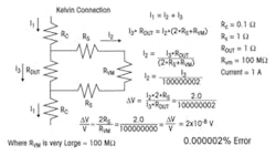
Figure 3. Measurement Accuracy Using Kelvin
Design Requirements
Contact Optimization
Both the pad and leaded Kelvin-ready schemes use a modified, rigid, one-piece contactor (in this case, the Johnstech ROL™ 200). The gap between the force and sense contacts was optimized by finite element analysis (FEA) to maximize the sense contact life. Monte Carlo analysis with manufacturing tolerances was used to prevent shorting.
The force contact has an existing rigid design to provide the best current-carrying capability, highest RF bandwidth, and the best self-cleaning wipe function to break through oxide layers present on many device pads. The flexible sense contact design features a smaller wipe function with a more pointed contact probe for accurate voltage measurements. Also, it routes sense signals away from the force signal to facilitate easier board layout and decoupling part placement.
The design uses the alignment plate, or cover, to keep the sense contacts in place. Removing the alignment plate results in access to the sense contacts, making it easy to replace them.
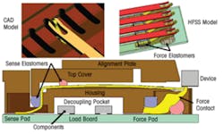
Figure 4. Device Interface View of Kelvin System
To show the relationship between the sense and force contact, Figure 4 depicts an isometric CAD view along with a high-frequency structure simulator (HFSS) top view of the Kelvin-ready contactor without the housing and alignment plate. The bottom of the figure illustrates the side view of the Kelvin-ready system showing the housing, cover for handlers that have precise placement capabilities, and the alignment plate.
The sense contact color was changed to red in the upper right HFSS view to better show contrast to the force contact at the device interface in the figure. The HFSS side view on the bottom depicts both contacts: in normal test mode and in the compressed state. The force contact’s self-cleaning wipe function is left to right, and the sense contact’s wipe function is up and down.
These two different wiping motions tend to move away any debris that might form, such as tin oxide from the device pad or molding debris from sawed packages. Both mechanical FEA simulations and measured data from extensive lab experiments and customer beta site testing showed that the life of the product was extended. Sense contacts routinely lasted more than 1,000,000 insertions, even when contacting devices using NiPdAu plating, which is much harder than the matte tin plating found on less expensive packages.
Field Configurability
Kelvin measurements aren’t always needed, so for normal RF, analog, or mixed-signal devices only the ROL™200 force contact needs to be installed into the housing. This handles any scenario up to 20 GHz.
If precision measurements are required or a feedback loop is needed to reduce false failures, the Kelvin-ready sense contacts then could be installed on one, a few, or all of the signal lines.
Not all device I/Os require measuring very small voltages and currents. With a configurable and reusable Kelvin-ready housing, the customer only needs to change the sense contact configuration and replace the load board with the one that corresponds to the DUT. If the type of handler is known when the test contactors are ordered, the design can accommodate the same contactors in production. This reduces the need for procuring extra contactors for low-volume production runs.
Load Board Simplification
On a load board set up to do testing on a handler for both Kelvin and a differential RF signal, the low-frequency lines and Kelvin-ready sense lines are routed to internal layers separated from the top-layer RF signals by a ground plane. The RF differential lines run parallel to each other and are routed directly to two connectors on the edge of the board.
Adjacent ground traces on either side of the differential pair use vias to provide a high isolation fence to the ground plane to enhance signal integrity and shield adjacent lower frequency lines. If decoupling parts were needed, they would be placed between the force and sense pads, their bodies protruding into the decoupling pocket shown in Figure 4.
Test Results
Increased Mean Time Between Assists
Extra switches can be added to the Kelvin circuit to help determine if cleaning or maintenance is required. When a device fails, the switches can provide a feedback path that is measured and compared to some baseline resistance. If the value is above the path resistance limit, the contacts are dirty, debris is present in the contactor, or the contactor is broken and causing a false failure. If the loop-back circuit resistance is lower than the feedback limit, then the part is determined to be bad. If the loop-back circuit resistance is higher than the feedback limit, the part could still be bad, but the contactor definitely needs to be cleaned before the device can be remeasured.
Because many packaged devices are completely tested in a fraction of a second, the force and sense contact resistances are not tested for every device. Many times, they are only checked if the device fails to determine if cleaning is needed. Using this checking method helps reduce false failures. In many cases, it also eliminates retesting parts and determines when maintenance is needed on the contactor.
A new material promises even longer life for the force contacts. Data taken for both soft matte tin and harder NiPdAu device leads supports a life expectancy of at least 500,000 test insertions for the force contact. Because the sense contact has a smaller wipe function, other test data has shown similar results to beyond 1,000,000 insertions. Actual results depend on the insertion speed of the device into the contactor. Results have shown life expectancy can be greatly exceeded if the insertion speed is lowered.
Because NiPdAu is a hard material and does not contain any oxides, a low-force elastomer can be used to help extend the contact’s life. For NiPdAu testing, the average contact resistance is very flat, and its standard deviation is less than 5 mΩ for the entire test.
Reducing False Failures
Checking the Kelvin circuitry every time a failure occurs eliminates the need for devices to be rechecked. Since the sense contact is only measuring a voltage at the device and you know the input current, you can maintain a stable DC power into the device. With a Kelvin feedback system, you can tell which parts pass for a given constant input. This also may support up-binning of devices with better performance, allowing them to be sold at a higher price.
On a rigid, one-piece contact, the data on one force/sense pair has much less variability than a similar spring-pin pair, which has three to five moving parts that may or may not make contact with each other at the same locations. For that reason, it might be advantageous to use Kelvin on the voltage lines and calibrate the data for the rest of the connections to the package.
With the device still in the contactor, the loop-back can determine if either the force or sense contact is not connecting to the device pad. If so, an open will be measured by the ohmmeter. A short between the force and sense can only be measured by running a signal through the feedback network without a device present. If a short is measured, the force and sense are shorted together. If either a short or open occurs, the testing should be stopped and the contactor serviced.
Device
Increased Yields
For a device sufficiently sensitive to contact resistance, big improvements in yield can be attained using a self-cleaning Kelvin-ready contacting system. In an actual non-Kelvin application involving an automotive voltage monitoring device, the contactor had to be cleaned more often, resulting in yields slightly above the 90% limit the customer expected.
For this device, a yield falling below 90% triggered a cleaning interval or investigation into the type of failures. Because there were no false failures when the same parts were subjected to Kelvin testing, there was no need to retest parts that failed at ambient. This reduced the number of parts to be tested at cold and consequently increased tester efficiencies.
The same contactor was used for both ambient and cold testing, the only difference being the handler was soaked at -40°C with the parts prior to testing. Each ambient or cold lot consisted of 8,000 to 10,000 packaged devices, almost 400,000 test insertions total. The yield at ambient was 95.98% and 97.46% for cold testing.
RF Performance
Most Kelvin applications have performance requirements for a small bandwidth and typically don’t need to process frequencies above 1 GHz. This allows Kelvin to be installed on non-RF lines in an RF device to provide feedback to improve on MTBA cycle times and reduce tester down times. This is important for customers who want to supply their devices with exactly the same DC power every time so variations in test data are only due to variations in the devices.
Without the sense contact attached, the -1-dB insertion loss bandwidth is about 33 GHz, and -3-dB bandwidth is beyond the 40-GHz upper test limit of the network analyzer used to measure the contact. Even with the sense contact attached and properly terminated, the -1-dB bandwidth for Kelvin testing is 3 GHz, more than sufficient for a Kelvin connection. A ground-signal-ground configuration is the preferred layout for high-frequency lines and signals that require minimal crosstalk between adjacent signals.
Conclusions
Contactor reusability is extremely important for reducing lead times and test costs. The Kelvin-ready solution offers the adaptability needed for today’s continuously changing test environments and provides the flexibility to accommodate future test needs. Using Kelvin techniques, customers can easily identify higher performing devices, increase the time between maintenance and cleaning cycles, and accomplish a variety of other test objectives.
About the Author
Jeff Sherry, P.E., is a senior RF/high-speed digital R&D engineer at Johnstech International with 27 years semiconductor industry experience. He received M.S.E.E. and M.B.A. degrees and has presented numerous papers at BiTS, ITC, and SEMI events and conferences. Johnstech International, 612-378-2020, [email protected]
About the Author
Comment About the Article
To join the conversation, and become an exclusive member of Electronic Design, create an account today!

Leaders relevant to this article: