Dealing with Increased MRI Field Strength
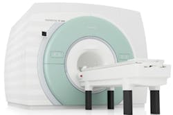
If you recently have had an MRI scan, you may have noticed that clinical machines with 3.0-Tesla (T) field strength have replaced many earlier generation 1.5-T machines. Higher field strength generally improves contrast and resolution but is not without challenges in many areas. In 2004, when 3.0-T machines had been available for only a couple of years, R. J. Stafford at the Anderson Cancer Center in Houston, TX, wrote, “Serious thought should be given to the workflow and routine scan protocols desired before deciding on a high-field unit over a 1.5-T system as many of the imaging protocols are still works in progress and various coils and technology considered standard are not yet available on the higher field systems.”1

Courtesy of Siemens Healthcare
Active shielding via a coaxial electromagnet, as shown in Figure 1, has become a common approach to reduce the size and weight of 3-T MRI machines. The main field coils are shown in blue and the outer shielding coils in orange.2
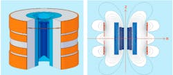
Figure 1. UltraShield Magnet Technology
Courtesy of Bruker BioSpin
According to Stafford, even with active shielding, 3-T machines weigh about twice as much as a 1.5-T machine—10,000 kg vs. 5,000 kg. Stafford estimated the weight of a 7-T unshielded magnet at 30,000 kg with an additional 100,000 kg of room shielding required to contain the fringe fields. Because fringe fields are higher in 3-T and 7-T machines, you may not be able to replace a current 1.5-T machine without significant site preparation costs.
Today, 7-T appears to be the B0 field strength most commonly used for high-field research. As occurred with the early 3-T machines, the range of available coils is not as great as for the previous generation. Nevertheless, higher field strength does facilitate tests for a number of conditions that were not practical at lower field strengths, and 7-T machines are poised to move beyond research applications. In particular, a 2011 paper segmented 7-T capabilities into brain, musculoskeletal, and body imaging, each area benefiting from an MRI with a high B0 field.3
Inside the Tube
All MRI machines operate by sensing changes in the alignment of atomic nuclei precession spin axes. The rate of magnetic moment precession is given by the Larmor frequency:
ω = γ B0
where: ω = Larmor frequency
γ = the gyromagnetic moment for a nucleus
B0 = the magnetic field flux density
The Larmor frequency is the frequency at which energy can be absorbed by the atomic nucleus and is the RF frequency driving the B1 coils. In contrast to the longitudinal and static B0 field, the B1 field is transversally polarized and pulsed.
For protons, the Larmor frequency is 42.58 MHz/T. Obviously, the repeated doubling of B0 from 1.5 T to 3 T and now to 7 T also doubles the Larmor frequency. For 7-T machines, the B1 coils are driven at approximately 300 MHz rather than about 65 MHz for a 1.5-T machine. It also is clear from the equation that any spatial variation in the strength of the B0 field directly affects the coupling between the B1 pulses and local nuclei.
Both mechanical and active shimming are used to correct spatial variations in the B0 field. Mechanical shimming relates to positioning iron plates that help shape the field. Active shimming involves electromagnets that add or subtract from the local field as required.
Protons are the nuclei most often used for tests and provide the highest signal level, but sodium-23 (Na), phosphorus-31 (P), carbon-13 (C), and fluorine-19 (F) atoms also figure in some medical procedures. The nucleus of each element has a unique gyromagnetic moment associated with it, so investigations need B1 coils capable of being driven at the correct frequency—11.262 MHz/T for Na, 17.25 MHz/T for P, 10.705 MHz/T for C, and 40.053 MHz/T for F.
Coils used to generate the B1 field are tuned to specific frequencies, which is the main reason that coils from low-field machines aren’t suitable for high T use. But, there’s more to the problem. As summarized in Stafford’s article, “At main fields of 3 Tesla and above, the B1 field sensitivity increases approximately linearly, but becomes increasingly inhomogeneous due to permittivity, conductivity, and the conformation of the patients…. The dielectric properties of tissue give rise to a region of hyperintensity at the center of the image referred to as field focusing. While some effects can be compensated for [by] improved coil design, such as transmission line, and post-processing methods based on simple models, signal intensity variations across the image are going to continue to be a significant challenge at high fields, driving and limiting development on both sides of the transmit-receive chain.”
Some B1 Design Trade-Offs
A paper presented at the 2013 IEEE IMS conference described an RF coil element based on the zeroth-order resonance (ZOR) exhibited by a composite-right-left-hand (CRLH) metamaterial transmission line (TL). Because of the interaction between the right-hand elements (series inductance and shunt capacitance) with the left-hand elements (series capacitance and shunt inductance) within each cell, a zeroth-order mode is supported in addition to the usual 2x, 3x,… nx resonant frequencies.4
The ZOR mode is important because it decouples a resonator’s physical length from its resonant frequency. In addition, a CRLH TL operating in ZOR mode is lossless because all points along the line are at the same voltage. Another term for the ZOR mode is an infinite wavelength mode.4
These properties are well-suited to an MRI machine’s B1 field coils. According to the paper, “The magnitude of B1 must be as constant as possible in the so-called field of view, which is always located in the human body. The longitudinally uniform magnitude is an inherent ZOR property.”4
In their work with ZOR TLs, the authors replaced previously developed microstrip-line stubs with short-circuited coaxial-line versions. The advantage of this approach is that the shunt inductor is shielded, and a high Q can be achieved. In addition, a balanced drive was used that avoided the sheath wave problems associated with feeding from one end.5
In another 2013 IMS paper, a different approach was taken to providing desirable B1 characteristics. Instead of the usual 25-cm length associated with 300-MHz resonance, 41-cm elements were used. “At 300 MHz, the excited dipole has an approximate 3λ/2 electrical length where the maximum of current is located away from the feeding position, exciting a longitudinal two-peak SAR distribution..,.. [The] passive shielding plate exhibits a half-wavelength eigen-resonance, which yields a transversal two-peak SAR distribution.”6 Distributing the peaks in this way creates four low peaks and a much more uniform field than in the 25-cm device.
Especially in high-Tesla machines, the local specific absorption rate (SAR) must be minimized. This is not easily accomplished with the large central E and H field peaks exhibited by 25-cm elements. Although the total magnetic field is reduced in the 41-cm elements, the field is much more uniform.
Both the CRLH TL element and the 41-cm B1 element were tested using a fluid phantom to simulate the human body. In each test, the element was placed 2-cm under a polyamide container filled with fluid (εr ≈ 45.3, δ ≈ 0.87 S/m). A SPEAG field probe was scanned at a distance 5 cm above the element to measure field strength. For both types of element, measured results corresponded well to simulations.
Accurate B-Field Measurements
A recent Metrolab Instruments report7 addressed three approaches to magnetic field measurement: Hall devices, fluxmeters, and nuclear magnetic resonance (NMR) technology. Each has its pros and cons.
Hall devices are low cost and easy to apply but typically work best in relatively high fields and achieve an accuracy of 1,000 to 100 ppm. Among drawbacks cited in the report, geometric and material imperfections contribute to an offset: the output will not be zero in a zero field. The Hall voltage only has an approximately linear dependence on the field strength. Hall devices are very temperature sensitive.
Fluxmeters appear very simple, consisting of a coil of wire and an integrator. If the coil is moved through a magnetic field, the integral of the coil voltage is equal to the change in magnetic flux. Dividing that value by the area of the coil gives the magnetic field flux density B. Accuracy to 10 ppm is practical. The SPEAG probe used to measure the experimental B1 fields was a fluxmeter probe.
A very useful fluxmeter property is the capability to find B anywhere along the integration path by using the partial integral up to that point. Nevertheless, on the down side, any voltage offset will be integrated and form part of the B measurement. A little bit of coil vibration can generate lots of noise. Coils expand as the temperature increases, making the measured magnetic field appear to be stronger than it is.
According to the report, “Fluxmeter mappers have traditionally been used in the high-energy physics community to map accelerator magnets and thereby to be able to predict the beam deflection. The most impressive recent project of this type is undoubtedly the Large Hadron Collider….Every one of the [LHC’s superconducting dipole magnets] was measured with a rotating-coil system….The reproducibility of the dipole measurement was estimated at 4 × 10⁻⁵ T.”
An NMR Teslameter operates on the same principle as an MRI machine. Rather than using a fixed RF frequency, NMR instruments sweep the RF frequency to determine the resonant frequency. By measuring the Larmor frequency and knowing the gyromagnetic moment for the NMR instrument’s sample material, the magnetic field strength is easily determined. Compared to other methods, NMR is extremely precise, has no drift, and measures the total field with an accuracy from 10 ppm to 1 ppm.
NMR is suitable only for uniform DC or slowly changing fields. In a nonuniform field, different parts of the sample will resonate at different frequencies. And, although perhaps 100 measurements/s can be made once the resonant frequency is found, scanning to find it may require that the field remain at a constant value for seconds.
The Metrolab article described an NMR-based mapper suitable for determining the 3-D characteristics of MRI B0 magnets. “The probe arrays and jigs shown in Figure 2 generate a map of the total field on the surface of a sphere. As long as there are no currents or magnetic material inside this sphere, and assuming the direction of the field is known, the field at every point inside the sphere can be calculated from Maxwell’s equations. Generally, we use an expansion in spherical harmonics to perform this computation.”7
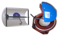
As can be seen from the figure, using an array of probes simplifies the required motion. The larger jig allows the probe array to be positioned at the required axial location and then rotated about the longitudinal axis. Repeating the process at a succession of longitudinal positions maps the entire volume of a torroidal MRI magnet. The smaller jig is suitable for mapping C-shaped MRI magnets.
7 T in Your Future
Today, there are no 7-T MRI machines approved for routine examination of patients. The machines that have been developed are being used for research and, according to wording on the Siemens Healthcare MAGNETOM 7T website, “may only be used for volunteer or patient examinations in the context of clinical studies according to applicable law.”
In addition to the Siemens MAGNETOM 7T, research MRI machines include the Philips Achieva 7.0T MRI research system and GE Heathcare’s MR950 whole body scanner for human patients. Bruker’s Biospin 7T microMRI scanner is suitable for small animal research.
A January 2010 press release stated, “The Varian, Inc. Magnet Technology Centre in Oxford, UK has manufactured over 80% of the world’s UHF MRI magnet systems. This, the world’s first 7-Tesla actively shielded magnet, was commissioned by a U.S. government research facility to demonstrate engineering leadership with the goal of having the technology adopted by clinical MRI system vendors. The magnet will be commissioned at its final site in the U.S. in early 2010.”8 Varian also worked with GE Healthcare in 2008-2009 to develop GE’s Discovery MR901 7T MRI system.
Active shielding helps make 7-T machines more affordable, although several sources estimate MRI cost at about $1M per T, so these units will never be inexpensive. Still, they do have advantages in specific cases such as brain and cardiology studies where their higher resolution is a great aid to correct diagnosis.
References
1. Stafford, R. J., “High Field MRI: Technology, Applications, Safety, and Limitations,” The University of Texas M. D. Anderson Cancer Center, May 2004.
2. Roth, G., “The 900 US2 Magnet: UltraShield Technology at 21.1T,” Bruker, Spin Report, 2005, 156, pp. 33-35.
3. Moser, E. et al, “7-T MR—from research to clinical applications?,” NMR in Biomedicine, Vol. 25, 2012, pp. 695-716.
4. Rennings, A. et al, “A MIM/Coaxial Stub-Line CRLH Zeroth-Order Series-Mode resonator used as an RF Coil Element for 7-Tesla Magnetic Resonance Imaging,” IEEE IMS2013 Proceedings.
5. Sanada, A. et al, “Novel Zeroth-Order Resonance in Composite Right/Left-Handed Transmission Line Resonators,” Asia-Pacific Microwave Conference, 2003.
6. Chen, Z. et al, “RF Coil Element with Longitudinal and Transversal Two-Peak Distribution for Low SAR 7-Tesla Magnetic resonance Imaging,” IEEE IMS2013 Proceedings.
7. Keller, P., “Technologies for Precision Magnetic Field Mapping,” Metrolab Instruments.
8. “Varian, Inc. Completes World’s First Actively Shielded 7 Tesla Whole-Body Research MRI Magnet,” Agilent Technologies, Jan. 19, 2010.
About the Author
Comment About the Article
To join the conversation, and become an exclusive member of Electronic Design, create an account today!

Leaders relevant to this article: