UFS PHY and Protocol Testing for Compliance
Universal flash storage (UFS) is a new memory standard developed through a collaboration between the MIPI Alliance and JEDEC. Now on version 2.0, UFS is specifically tailored for mobile applications and computing systems requiring high performance and low power consumption. UFS testing challenges include higher data rates that increase the importance of signal integrity in links along with the need for stress testing the receiver. With the use of multiple power modes, UFS is intrinsically dynamic in nature, which makes capturing protocol more difficult.
For designers accustomed to working with today’s computer-based high-speed serial standards and memory buses, M-PHY’s changeable gears, terminations, and low signal amplitude introduce a new set of testing challenges. For mobile designers who have been working with the slower D-PHY, the higher speeds available in M-PHY and UFS will create new signal integrity challenges to manage timing/jitter and noise. Receiver stress testing also will be a requirement for M-PHY’s high-speed gears (HS2, HS3).
The MIPI M-PHY specification realizes the MIPI Alliance’s vision of a single low-power, mobile PHY powerful enough to address existing and future mobile devices’ requirements. It is the mobile PHY of the future for smartphones and tablets and will likely power next-generation devices that merge the power of a PC with the responsiveness and long battery life of mobile devices.
D-PHY, the first MIPI PHY standard, was introduced in 2005 and can be found in many mobile devices today. D-PHY is commonly used to connect an applications processor to a camera using the MIPI camera serial interface (CSI) and to connect the applications processor to the mobile device’s display using the MIPI display serial interface (DSI). D-PHY’s reach has not extended beyond the camera and display due to inherent architectural limitations restricting the transmission rate to 1.5 Gb/s. This was not seen as a limitation several years ago but is too slow to handle the data traffic in today’s smartphones and tablets.
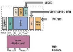
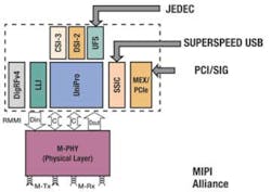
The M-PHY specification was designed for addressing all bus communications support in a mobile device with headroom for future scalability. This effort resulted in a serial, low pin-count embedded clock PHY that offers multiple transmission and power-saving modes. The M-PHY supports data rates from 10 kb/s up to 5.8 Gb/s, enough bandwidth to support the various data interfaces within a mobile device. Interfaces employing M-PHY now include several MIPI standards (CSI-3, DSI-2, LLI, UniPro, and DigRF), the USB SSIC standard, UFS, and more recently the M-PCIe standard. The interfaces are organized in a layered stack as shown in Figure 1.
UFS—Mobilizing Data
First published in February 2011, UFS is intended to be the most advanced specification for both embedded and removable flash memory-based storage in mobile devices. The initial data throughput for UFS is 300 MB/s over the bus in both uplink and downlink directions simultaneously without infringing on bandwidth needed for other applications. The UFS standard was developed, in part, because eMMC, the memory interface standard that had offered the best solution for most mobile devices, was unable to meet the mobile market’s scalability and performance requirements. Because UFS is a serial and scalable interface, it is targeted to replace eMMC for embedded flash interfaces in new and emerging designs.
UFS offers a low active power level and a near-zero idle power level that, combined with the power-saving attributes of M-PHY, can provide significant reductions in device power consumption. UFS adopts the well-known SCSI architecture model and command protocols supporting multiple commands with command queuing features and enabling a multithread programming paradigm. This differs from conventional flash-based memory cards and embedded flash solutions that process one command at a time, limiting random read/write access performance.
In September 2013, JEDEC published JESD220B UFS v2.0, which is an update to the v1.1 standard published in 2012. JESD220B UFS v2.0 offers increased link bandwidth for performance improvement, a security features extension, and additional power-saving features.
Coming Up to Speed on UFS Test
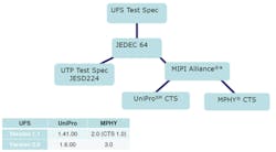
Although the physical layers of UFS are based on MIPI M-PHY and UniPro specifications, the test requirements are outlined in JESD224, which standardizes UFS testing. This document details test cases and procedures for measuring the behavior of UFS devices and compares those with the requirements of the UFS specification. The Universal Flash Storage Association (UFSA), formed in 2010 to promote the market adoption of UFS, is working to incorporate the test procedures described in the JESD224 document into a UFSA compliance test specification (CTS) for UFS product compliance certification.
As shown in Figure 2, designers also will need access to both UniPro CTS and M-PHY CTS documents and must join the MIPI Alliance for access to the documents and for implementation and licensing.
For designers already familiar with verification and characterization of high-speed serial links, M-PHY’s changeable gears, terminations, and amplitudes will introduce a set of testing challenges. For mobile designers, the high-speed serial standards will further increase the importance of maintaining the signal integrity of links with more emphasis on timing/jitter and noise. Receiver stress testing also is a requirement.
Compared to typical serial buses that are essentially on or off, M-PHY is much more dynamic with multiple power modes. This dynamic nature makes protocol capture challenging for FPGA-based signal decoding. The use of an oscilloscope with appropriate decode, trigger, and search capabilities will be necessary to verify the consistency of bus performance over time. Such tools as shown in Figure 3 enable trigger and search on control characters, symbols, patterns, and character error or disparity errors.
Although data rates are bound to continue to increase, currently the fastest M-PHY High Speed (HS) signaling mode is Gear 3, which operates at 5.83 Gb/s. At this speed, you’ll need an oscilloscope with at least 20-GHz bandwidth. Given the compact physical layouts used in mobile devices, signal access will be an ever-present challenge, and you’ll need differential SMA-based probes. Similarly, you’ll need the ability to de-embed interconnect loss.
On the receiver side, electrical compliance tests continue to be accomplished using an arbitrary waveform generator (AWG) as the signal source and BERT or a high-speed real-time oscilloscope functioning as a bit error detector. An AWG also lets you automate receiver and compliance testing for faster time to market and improved test accuracy and consistency.
Transmitter Test Solutions
In addition to joining the MIPI Alliance, designers coming up to speed on M-PHY and UFS link test requirements should spend time reviewing available test documentation, such as methods of implementation (MOI) produced by Tektronix and other major test providers.
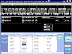
M-PHY transmitter testing involves approximately 1,000 tests across different combinations of gears, subgears, amplitudes, and termination for each lane under test. Setup and reporting requirements are demanding as well. To make the testing less onerous, oscilloscope software is available to automate M-PHY testing. Such software reduces the overall test complexity and the time required to test devices and generates a printable report. The report covers the various test combinations and provides a pass/fail summary table along with margin details, optional waveform captures, and eye diagrams.
Signal Integrity
For developing systems using UFS, the test emphasis is on debug from the protocol layer to the physical layer, computer system validation, and embedded system debug and validation. Direct signal observations and measurements are the most efficient way to discover the causes of signal integrity-related problems.
Signal integrity measurements involving UFS are carried out using the same familiar instruments found in almost any electrical engineering lab. These instruments include the logic analyzer and the oscilloscope with probes and application software rounding out the basic toolkit. In addition, signal sources will be used to provide distorted signals for stress testing and evaluation of new devices and systems.
Tools that support protocol decode are available for seamless PHY and protocol views similar to that shown in Figure 4. This example shows the linkage of UniPro/UFS packet with an oscilloscope M-PHY waveforms. Such views greatly assist designers in pinpointing the root cause of errors with the protocol debug placed right below the oscilloscope waveform.
Receiver Testing for M-PHY
Receiver testing has many waveform-generation needs including non-return to zero (NRZ) signaling, pulse width modulation (PWM) signaling, 8b/10b encoding, reference clock, differential signal generation with common-mode DC, and the addition of jitter impairments such as ISI, Pj, and Rj.
Loopback mode is the most common mechanism for receiver testing, primarily for BERT. In M-PHY loopback testing, the receiver routes and retransmits a recovered M-PHY signal through the transmitter without decoding 8b/10b symbols. Loopback mode requires that both the transmitter and receiver use the same mode and gear. An oscilloscope-based error detector or BERT can perform this testing.
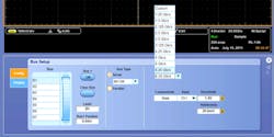
Similar to the transmitter side, software that automates Rx test set and execution can reduce complexity and save time. In addition to an oscilloscope, Rx testing also requires an AWG. A typical configuration is shown in Figure 5. The software typically supports error count testing and provides options to modify the test setup according to device configurations such as the high-speed gear, test time, or loopback duration.
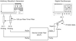
Before the receiver test can start, the device under test must be put in loopback mode. Once loopback is set on the DUT, the AWG sends a burst mode signal with recommended patterns for all measurements. The software allows the user to configure the loopback settings initially and retain them for subsequent test executions by sending the signal continuously during the transition from one test to another. By working together, the AWG and the oscilloscope error detector can complete each measurement in about three minutes.
UFS Here to Stay
With all the momentum behind UFS from JEDEC with the recent publication of the JESD224 test standard, the message is clear—UFS is here to stay. The publication of JESD224 is a clear indication of support coming from memory manufacturers and consumer device and mobile OEMs toward driving broad UFS implementation and adoption.
Now on v 2.0, UFS has emerged as the most advanced specification for both embedded and removable flash memory-based storage in mobile devices. Looking ahead, UFS compliance testing will benefit from an open test house/certification process and the release of vendor-based MOI. Also on the horizon, the UniPro working group within the MIPI Alliance is beginning work on the USF 3.0 specification and actively gathering input—all signs of an emerging standard gearing up for long-term success.
About the Author
Chris Loberg is a senior technical marketing manager at Tektronix responsible for oscilloscopes in the Americas Region. He has held various positions with Tektronix during his more than 13 years with the company, including marketing manager for Tektronix’ Optical Business Unit. Loberg also had similar marketing positions with Grass Valley Group and IBM and earned an M.B.A. in marketing from San Jose State University. [email protected]
About the Author
Comment About the Article
To join the conversation, and become an exclusive member of Electronic Design, create an account today!

Leaders relevant to this article: