Courtesy of Keysight Technologies
The low-frequency LCR meter is the instrument of choice for many component measurements. Although manufacturers have developed different measurement techniques, fundamentally the meter compares the magnitude and phase of the voltage across an unknown impedance to the magnitude and phase of the current applied to it.
The ratio Z = V/I in general is complex, having both a real resistive part and an imaginary reactive part. Alternatively, most modern LCR meters can compute the complex admittance Y of an unknown component. The choice of a series or parallel model to achieve the best measurement accuracy depends on the relative real and imaginary values.
To support L and C measurements that reflect how the components will behave in an actual application, many LCR meters include a bias voltage source as well as a bias current source. And, the actual signal level must be variable to accommodate cored inductors and other level-sensitive components. The output impedance also is variable in some meters.
Bridge or Meter?
There is a distinction between the terms LCR bridge and LCR meter, although they are used interchangeably today. The early LCR bridges were based on the Wheatstone, Maxwell, Hay, or Schering circuit and compared the unknown component to a variable component in one leg of the bridge. However, as more and better electronic components became available, a true bridge circuit became less necessary, especially at low frequencies.
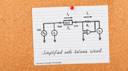
So-called auto-balance bridge technology is used in many LCR meters today. The virtual ground that the op-amp provides via feedback through the reference resistance Rf is equivalent to the null indicator in a bridge. Balance is achieved because the current fed back through the resistance R is exactly equal in magnitude and opposite in phase to the current through the unknown Zx.
As stated in an Agilent (now Keysight) Technologies document, for frequencies below about 100 kHz, LCR meters typically “employ a simple operational amplifier for [the] I-V converter.… Wideband LCR meters and impedance analyzers employ the I-V converter consisting of a sophisticated null detector, phase detector, integrator (loop filter), and vector modulator to ensure a high accuracy for a broad frequency range.”1
The QuadTech 7600, still available from IET Labs, simultaneously measures the voltage across the unknown component and the voltage across a reference resistor in series with the unknown. This technique is known as the I-V method in which both voltage and current are directly measured without the need for a null detector or feedback loop.
Transformer testing is supported on several LCR meters. In addition to basic measurements, these instruments also can determine the turns ratio and the mutual inductance between the primary and secondary coils.
Courtesy of Keysight Technologies
Modern LCR Meters
IET Labs provides a broad range of LCR meters and bridges, having acquired the GenRad instrument line in 2000 and several models of QuadTech LCR meters in 2012. The 1693 precision LCR meter makes capacitance measurements from 10 mF at 500 frequencies from 12 Hz to 200 kHz and with a basic 0.02% accuracy.
The Model 1659 Digibridge measures five impedance parameters with 0.1% accuracy, has four test frequencies, and features a built-in test fixture. The handheld Model DE-6000 LCR meter allows four-wire Kelvin measurements and also is available from IET. Five test frequencies cover the 100-Hz to 100-kHz range: 100 Hz, 120 Hz, 1 kHz, 10 kHz, and 100 kHz. An optional USB interface supports LCR measurement storage.
Thurlby Thandar Instruments’ Model LCR400 is an LCR meter with a limits comparator that provides a binning capability for production applications. As described in the LCR400 datasheet, “Up to eight pass bins and two fail bins can be defined.” Another feature often found in this class of meter is provision for nonvolatile test setups—nine for the LCR400.
Wayne Kerr Electronics’ precision magnetics analyzer Model 3260B provides from 1 mA to 1 A of bias current but handles up to 125 A from external sources such as the company’s Model 3265BQ 25-A DC bias unit—five supplies can be used in parallel. Measurements include Z, θ, L, C, R (AC and DC), Q, D, turns ratio N, leakage inductance, interwinding capacitance, and resonant frequency.
According to the 3260B datasheet, this instrument is especially suitable for measuring telecom transformer parameters such as insertion loss and return loss. In addition to driving an external plotter to graph any of the measurement functions against frequency, AC drive level, or DC bias current, the unit supports a selection of telecom line impedances and terminations as well as a user-specified simulated damping network and blocking capacitor.
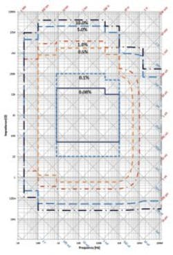
The Agilent 4294A model has been replaced by the Keysight Technologies’ E4990A Series impedance analyzer with a 20-Hz to 10-, 20-, 30-, 50-, or 120-MHz frequency range depending on the model. In addition to the extended frequency range compared to the 4294A, the E4990A instruments feature a Windows 7 platform, a 10.4-inch touch screen, and a smaller footprint.
The basic 0.08% accuracy applies to a combination of test frequency and component values spanning a few decades. Other contours show the combinations for which 0.1%, 0.5%, 1.0%, 5.0%, and 10.0% accuracy apply. The best typical performance is 0.045%, but when the E42941A impedance probe or the E42942A terminal adapter is used, the most accurate guaranteed contour is 1%.
The Model 3550 from Tegam features a 5-MHz upper frequency limit together with 18 measurable parameters, 0.1% basic accuracy, and 18-ms measurement speed. The company’s Model 3525 boasts 0.08% accuracy, slightly faster 15-ms measurement speed, and a three-year warranty vs. the 3550’s one-year. Both meters have standard RS-232-C and I/O interfaces with optional GPIB or BCD. More than 4,500 frequencies are selectable with 0.01% accuracy. This instrument uses Kelvin connections, and chip tweezers are optionally available to connect to SMT components.
With 40,000 counts, B&K Precision’s Model 879B handheld LCR meter measures L, C, R, D, Q, θ, and ESR at 100 Hz, 120 Hz, 1 kHz, and 10 kHz with a basic 0.5% accuracy. Auto ranging, data hold, and automatic calculation of secondary parameters combine to improve ease of operation. SCPI commands communicate via USB using downloadable software for data logging and front-panel emulation.
Operating up to 100 kHz, the Stanford Research Systems Models SR715 and SR720 use two displays, like B&K’s 879B, to show both the primary and secondary parameters. SRS provides two groups of five-digit LED displays while B&K uses the full 40,000-count resolution for only the primary measurement, dropping to 10,000 counts for the secondary.
Measurement speed is yet another factor that distinguishes one instrument from another, the SRS 715/720 taking two, 10, or 20 samples/s followed by a user-selectable number of averages to improve accuracy. The two models primarily differ on basic accuracy, 0.2% for the SR715 and 0.05% for the SR720.
The QuadTech Model 1730T LCR meter also performs turns ratio transformer testing and is available from Chroma Systems Solutions. This instrument offers 10 test frequencies from 50 Hz to 100 kHz and measures 14 parameters with display capabilities for any two. Source impedance is programmable from 10 Ω to 100 Ω, and up to 50 test setups can be stored and recalled. Basic accuracy is 0.1%, enhanced by open/short zeroing that reduces the effects of error sources between the DUT and the calibrated connection to the instrument.
Hameg Instruments, a Rohde & Schwarz company, makes the HM8118 LCR bridge with 0.05% basic accuracy, internal voltage and current bias sources, and transformer parameter measurement. The 20-Hz to 200-kHz frequency range is covered in 69 steps with 100-ppm accuracy. Front-end protection is a feature mentioned in some datasheets and either is provided internally, as in the HM8118 for up to 1 Joule of stored energy, or externally in the interface between the DUT and the instrument.
Charged capacitors can easily store sufficient energy to damage instrument input circuitry unless protective measures are in place.
Another important feature of the HM8118 is galvanic isolation for USB, RS-232, or optional GPIB interfaces that may connect the instrument to a computer. Isolation eliminates the ground loops and interference or possible damage that can occur when two pieces of equipment having different ground references are connected together.
The LCR-8110G LCR meter from GWInstek has 0.1% basic accuracy and one of the widest test frequency ranges for this class of instrument: 20 Hz to 10 MHz. Other models in the LCR-8000G Series have either a 5-MHz or 1-MHz upper limit. The meters feature a graph mode that uses the instrument’s display to present a component’s impedance as a function of the test frequency or test voltage sweep. The test frequency is continuously variable with five digits of resolution.
Summary
Before buying any instrument, you need to determine whether it will be used for production or development. Product designers generally don’t need a binning capability but may want more than four or five test frequencies. If you’re working with transformers, having built-in analysis capabilities will be useful. And perhaps the two parameters that most affect price are frequency range and measurement accuracy. Honestly assessing how much of each you really need will help secure the best solution to your component measurement application.
Reference
Agilent Impedance Measurement Handbook 4th Edition, Keysight
Technologies, September 2013.
For more information
B&K Precision
Chroma Systems Solutions
GWInstek
Hameg Instruments
IET Labs
Keysight Technologies
Stanford Research Systems
Tegam
Thurlby Thandar Instruments
Wayne Kerr Electronics


