Visiting IBM’s boat-shaped EMC chamber
In the late 1980s, IBM contracted to have a 10-meter EMC semi-anechoic test chamber built at the company’s Research Triangle Park, NC, facility. Installing such a large chamber is not a simple undertaking because it can involve site preparation, structural building design, local permitting, provision of large amounts of power and cooling often required by the equipment being tested, and the control of chamber humidity to optimize absorber performance.
A 10-meter chamber specified to meet ANSI’s ±4-dB NSA requirement at frequencies below 100 MHz was a particularly daunting project given the limited absorber technology available at the time. Ferrite tiles for use as absorbers up to 100 MHz had been patented in Japan in 1969, but the tiles were expensive and difficult to ship in large quantities.1 Instead, the IBM chamber used 8-ft long carbon-impregnated pyramidal foam absorbers to achieve the necessary performance below 100 MHz.
According to EMC industry veteran Brian Lawrence, the Research Triangle Park facility was not the first 10-meter chamber to be built for IBM using this absorber technology. These earlier rectangular chambers had never quite achieved ANSI requirements during vertical polarized testing, and empirical investigations indicated unacceptable reflections from the vertical 90-degree corners where 8-ft pyramids could not be installed. To eliminate these corner reflections, the new chamber design was boat-shaped with chamfered corners, allowing the long pyramidal absorbers to cover these problem areas.
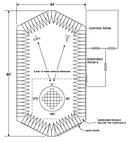
As Figure 1 shows, the overall dimensions were 80 ft x 44 ft. Subtracting twice the length of the absorbers leaves a working space of about 64 ft x 28 ft—sufficient to establish a reasonable quiet zone and accommodate 10-meter measurements. Exactly how well such long absorbers might work wasn’t fully understood until a Ray Proof and IBM-funded project with the University of Colorado at Boulder developed suitable simulation software in the 1980s that led to production and factory testing techniques of effective absorbers up to 12-ft long.1
In 1995, EMC industry leaders EMCO, Rantec, and Ray Proof combined their resources to create EMC Test Systems (ETS). Both Rantec and Ray Proof were EMC chamber pioneers, Rantec having built several military chambers in the 1970s and Ray Proof having developed better absorbers for use in the earliest successful 10-meter chambers. After the acquisition of Lindgren RF Enclosures in 2000, the company name changed to ETS-Lindgren.
Initially, the IBM chamber was used to test products manufactured at the Research Triangle Park facility. IBM also offered EMC design guidance and full compliance testing as a service to other companies. In a brochure titled EMC Solution Services, IBM described the facility as an RF shielded semi-anechoic chamber suitable for FCC Class B and ANSI C63.4 3-meter and 4-meter emissions testing and for several types of immunity and susceptibility testing including ESD, radiated EM, powerline switching, lightning surge, and EFT. Consulting services were available to help with materials selection, circuit design, and even cost reduction while ensuring EMC compliance.
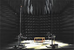
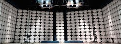
Figure 2, scanned from the brochure, shows the interior of the chamber as it would have appeared in the 1990s and early 2000s. Note that some of the long absorbers are drooping a bit and that the chamber in general is very dark.
In 2007, ETS was awarded a contract from IBM to upgrade the chamber, adapting it to accommodate the very large and high-power mainframes built at IBM’s Poughkeepsie, NY, facility. Refurbishment included installation of a 25,000-lb capacity 6-meter diameter turntable and its drive mechanism to replace the original 3,000-lb, 4.5-meter facility.2 In addition, the 8-ft pyramidal absorbers were replaced with 5-ft ferrite hybrid pyramids, which both improved the RF performance and provided additional space within the chamber.
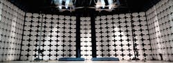
More recently, white end caps were installed on the absorber. The end caps protect the pyramids and also brighten the chamber’s appearance but have no influence on the RF/microwave performance.
The power and cooling utilities are made available in the full-height original Exerciser Room B below the turntable, as shown in Figure 1, and in extensions to it that were part of the 2007 work. Here, up to 400 kW of “electronic power” is available—electronic power meaning power at different frequencies and amplitudes than that supplied from the onsite substation. A similar amount of raw mains power also is available and enters the room via 600-A ETS filters. Originally, only 36 kW was available. In addition, large amounts of chilled water at the required flow rates are on hand for those mainframes that rely on water cooling. According to reference 2, HVAC capacity tripled.
Reference 2 is recommended reading for anyone contemplating chamber refurbishment, even if not on the very large scale of the IBM undertaking. Because the size of the EUT had significantly increased, the normalized site attenuation (NSA) volume doubled—meaning that the actual chamber performance became critical. Originally, measurements confirmed that the chamber was within the ±4-dB limits, but only just. Simulations based on the new absorbers generally were within ±3 dB with one combination of turntable and receive antenna positions showing a 3.5-dB deviation at 10 MHz. The article concluded, “Once the project was completed, the actual testing showed the site attenuation test results met the required ±4-dB requirement with a comfortable margin.”2
I was invited to join ETS’ Glen Watkins, director of marketing, and a few other ETS employees on what essentially was a reconnaissance mission to the IBM facility prior to the ETS-IBM tour for about 100 EMC Symposium 2014 attendees.
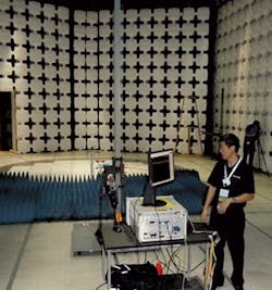
Figure 3 shows Zhong Chen, currently the product manager, RF materials at ETS and previously a senior principal design engineer at the company, performing a live time-domain measurement in the chamber during the tour.
10-Meter chambers today
Because of advances in absorber technology, a modern rectangular ETS FACT 10 EMC chamber with a 6-meter quiet zone measures 71.5 ft x 43.5 ft x 29.8 ft between shielded surfaces. Although smaller than the IBM chamber, this still is a sizable structure, being a bit wider and a little shorter than a doubles tennis court. According to the datasheet, “At 10-m test distance, ETS-Lindgren guarantees a NSA deviation better than ±3.5 dB from theoretical NSA within a cylindrical quiet zone of 3 m, 4 m, and 6 m diameters over the frequency range of 30 MHz to 1 GHz.” The 6-meter quiet zone quoted is the largest offered and requires the maximum size chamber with 1.5-meter pyramids. The plan-view dimensions reduce to less than 65 ft x 40 ft for the 3-meter and 4-meter quiet-zone chambers.
In spite of the proliferation of large test chambers, determining their actual performance is not straightforward. CISPR 16-1-4 specifies a test method used to determine a chamber’s site voltage standing wave ratio (sVSWR), a measure of chamber uniformity for frequencies above 1 GHz. However, in a recent paper by Chen, the present CISPR method is shown to undersample the standing wave pattern because successive positions of the transmit antenna neither cover a great enough distance nor do so with sufficiently small increments. In addition, the 50-MHz minimum required frequency increment is shown to be too coarse to guarantee that the maximum standing wave reinforcement will occur in a particular chamber.
Instead of the CISPR 16-1-4 frequency-domain approach, Chen proposes a time-domain method in which reflections can be separated and treated individually based on their time delay. This technique allows appropriate reflection coefficients to be associated with each reflection, leading to a better estimation of the true chamber performance. The approach uses the same test setup as CISPR 16-1-4, and according to Chen’s paper, “… is faster, less error-prone, and… more thorough in achieving the true sVSWR of a site under test.”3
Most importantly, the time-domain method not only correlates to the results obtained by the CISPR method, but also provides debugging capabilities because chamber users can see precisely where and by how much their chamber may be under-performing. The proposed method currently is being written into a new standard by the ANSI ASC C63 committee, reference draft standard C63.25.
Acknowledgement
Thanks to ETS-Lindgren for help in preparing this article.
References
Lawrence, B., “Anechoic Chambers, Past and Present,” Conformity, April 2001.
Archambeault, B., et al, “Site Attenuation Prediction for Refurbishing an older EMC Chamber,” In Compliance, August 2009.
Chen, Z., Uncertainties in sVSWR and A Proposal for Improvement Using Vector Response Measurements, ETS-Lindgren, 2014.
About the Author
Comment About the Article
To join the conversation, and become an exclusive member of Electronic Design, create an account today!

Leaders relevant to this article: