Severe electrical disturbances can be caused by nuclear blasts. A weapon exploded at least 40 miles above the earth does no direct pressure or temperature damage but generates a large high-altitude electromagnetic pulse (HEMP) that has three components—an extremely fast, high-amplitude E1 pulse, E2 similar to lightning, and E3, which is a slowly changing magnetic-field phenomenon that can induce huge currents in very long conductors such as power and communications lines. The effects of E3 are similar to geomagnetic disturbances (GMD) caused by a large solar storm and were the theme of a previous EE-Evaluation Engineering article.1
The E1 pulse was succinctly described by Dr. George Baker, Professor Emeritus at James Madison University and principal staff member of the EMP Commission, in his testimony before a congressional hearing on EMP. He said, “The fast EMP field, also referred to as E1, is created by gamma ray interaction with stratospheric air molecules. It peaks at tens of kilovolts per meter in a few nanoseconds and lasts for a few hundred nanoseconds. The broadband frequency content of E1 (0 to 1,000 MHz) enables it to couple to electrical and electronic systems in general, regardless of the length of their penetrating cables and antenna lines. Induced currents range into the thousands of amps. Exposed systems may be upset or permanently damaged.”2
E1 EMP can be particularly damaging because the pulse covers hundreds or thousands of square miles. And, pulse intensity is not necessarily a function of weapon size. Rather, the important factor is the amount of gamma radiation generated. Several sources refer to development of weapons with extraordinary levels of gamma ray production because of the extreme effects that a very large E1 pulse could have on an enemy country’s infrastructure.
Hardening and testing
Cold War experiments
HEMP is of special importance to the military. A recent threat report proposed a three-component strategy for coping with HEMP: deterrence, active defense, and improved infrastructure resilience. The report examined the interdependencies among the three components, making the point that for effective deterrence, enemies must understand that they cannot win. “… the Unites States must ensure it could retaliate in a manner that would overwhelm whatever value the opponent might anticipate from such an attack.”3
Military ordnance, communications, transportation, and command and control must be made immune to HEMP to maintain the capability to retaliate. In many cases, conventional shielding and grounding practices provide adequate protection. Some critical signal lines might be changed from copper to fiber-optic cable with well-shielded end points. Using these kinds of techniques, the military generally has demonstrated success in hardening systems against HEMP.
To better understand the effects of HEMP, a series of atmospheric nuclear tests was conducted. The 1962 Starfish Prime explosion, part of Operation Fishbowl, is one often referenced. It used more and better instrumentation than previous atmospheric tests, but many readings still were off-scale. Although the effects of the E1 pulse could be quantified, the theory behind its generation was not fully understood until Langmire’s work in the early 1980s.4 But, even without the underlying theory, field strengths and pulse characteristics were known and could be allowed for when designing hardened equipment. And, these same “threat-level” characteristics guided development of a large number of E1 simulators that were used to verify that critical system hardening actually had been achieved.
The Soviet Union also performed a series of atmospheric atomic tests and arrived at similar conclusions. That country and several others developed the non-nuclear technology required to simulate high-energy E1 HEMP. During the 1960s and 1970s, many very large-scale simulators were built with a wide range of capabilities.
Simulators
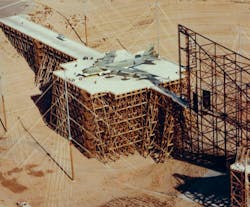
Dr. Carl E. Baum was one of the United States’ leading simulator designers, primarily working at Kirtland Air Force Base in New Mexico. The largest of his designs was the ATLAS-I (Air Force Weapons Lab Transmission-line Aircraft Simulator) built during the 1970s and used until 1990 (Figure 1). Also known as the Trestle, for obvious reasons, the simulator was almost entirely constructed of wood so that it would be electrically invisible to simulated E1 pulses.

To minimize the effect of the ground, as would be the case when a plane was flying at the time of an explosion, the structure was 12 stories high. B-52 bombers as shown in the image and other very large planes were towed to the 200-ft x 200-ft working area of the simulator where they were subjected to suitable pulses. The Trestle simulator used two 5-MV Marx generators as the pulse source, one positive and the other negative, driving opposite sides of a huge waveguide—the high metallic structure at the right end of the wooden construction.5
Although the actual peak E-field levels were classified, 50-kV/m generally was accepted as a reasonable “threat-level” value. See the sidebar for a short discussion of Marx generators. In many simulators, pulse amplitude could be varied so that weaknesses in the hardening could be found without actually destroying the system under test.
In an interview in 2010, Dr. Baum “… reflected on the necessity of building the $60 million Trestle, both symbolically and practically.” He explained that if an atomic bomb were detonated a couple of hundred miles over the United States, the EMP that was produced could wipe out computers, the entire electrical power grid, the telecommunications infrastructure, and satellites. He said, “The nuclear EMP was an important technical problem during the Cold War because it was vital that the Soviets could not attack an EMP Achilles’ heel. Testing of the strategic systems was important to convince them of this fact.”6
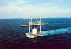
During the time period that the Trestle simulator was testing airplanes, the Navy needed to determine that a ship’s electronics had been hardened to the required degree. The land-based EMPRESS I electromagnetic pulse radio frequency environment simulator for ships simulator at Point Patience in Solomons, MD, was used for several years, but, according to a 1984 article, “Its power is limited, however, and so is the size of the ship it can accommodate; destroyers and aircraft carriers cannot navigate the narrow channels to get near it. EMPRESS II would be barge-mounted. Its 130-foot-high antenna would be able to shoot 7 million volts, whose intensity would diminish rapidly with distance, toward a nearby warship.”7
EMPRESS II (Figure 2) was constructed and used only once, in 1993, to test the USS Anzio, a Ticonderoga-class guided missile cruiser. According to a report in the Naval Engineers Journal, “… [The test] had two primary objectives. The first objective was to completely baseline the survivability of shipboard equipment at EMP field strengths high enough to obtain accurate test data but low enough to minimize equipment damage from multiple electromagnetic pulses. The second objective was to determine the ability of the ship to fight after a full-scale level EMP. Both objectives of the EMP trial were successfully met. The results verified pretrial hardening predictions and efforts, revealed hardening weaknesses, and provided a baseline for future hardening initiatives. Empress II was dismantled shortly after the trial.”8
EMP today
A 2010 article on the Navy’s CHIPS website picked up the narrative several years after the breakup of the Soviet Union in 1991. “With the collapse of the Soviet Union, and no perceived threat, the military’s investments in EMP assessment capabilities were significantly reduced…. Dormant for more than a decade, the U.S. Navy’s Electromagnetic Pulse Program is being revived through the Naval Sea Systems Command (NAVSEA) Office of the Director of Force Electromagnetic (EM) Effects and Spectrum Management. The program’s immediate goals include establishing cognizance about current standards for system acquisition as related to EMP survivability, assisting with developing standards and methodology to test and assess future systems, assessing the current posture of mission-critical systems with regard to EMP survivability, and coordinating with other Department of Defense (DoD) services and entities to share EMP resources and information.”9
China became the fifth atomic power in 1964, joining France, the Soviet Union, the United Kingdom, and the United States—and all have signed the 1970 Nuclear Non-Proliferation Treaty. In addition, India (1974), Pakistan (1998), and North Korea (2006) also have declared they have nuclear weapons. Israel is thought to have nuclear weapons but has not formally declared so. These are the countries we know about.
As can be seen from the dates that nuclear weapon capabilities were acquired, the Cold War period from the mid-1970s until the failure of the Soviet Union in 1991 was relatively stable. From the aspect of knowing who your adversaries were and their nuclear capabilities, there weren’t a lot of surprises. It was practical to invest in the design and construction of large-scale EMP simulators both to prove our retaliatory capabilities and to convince others of them, as Dr. Baum stated.
With additional nuclear states as well as numerous nonstate groups that would like to acquire nuclear capabilities, EMP again had become a very real existential threat by the late 1990s. This was recognized by the U.S. House Armed Services Committee that established the Commission to Assess the Threat to the United States from Electromagnetic Pulse Attack (the EMP Commission) under the National Defense Authorization Act of 2001. The commission was active from 2001 through 2009 and reported on the country’s vulnerabilities in both 2004 and 2008. Many of the people involved still provide information to various congressional bodies today.
Nevertheless, the commission also has been viewed as having a political agenda. An article on the Right Web website, a project of the left-leaning Institute for Policy Studies, stated, “Sponsored by Rep. Roscoe Bartlett (R-MD), the EMP Commission served as a cornerstone of right-wing advocacy on national defense policy. Advocates seeking to spread alarm about the purported threat of EMP attacks, which would involve the detonation of nuclear weapons in the upper atmosphere to generate a pulse that would knock out electronics-based infrastructure, have repeatedly used the findings of this commission to advocate increased funding for costly weapons programs such as missile defense and push alarmist notions that ‘rogue states’ like Iran and North Korea pose an existential threat to the United States.”10
As discussed in reference 1, it’s easier to disentangle arguments about E3/GMD protection than it is to deal with E1 EMP: That a massive GMD event will occur in the future is certain while the probability of an E1 pulse occurring is less—unknown—but less. Still, the consequences of not protecting against E1, were such a pulse to occur, are huge. Therefore, it is important to note recent EMP-related activity such as the NAVSEA initiative as well as renewed interest in using the Cheyenne mountain facility to protect critical military communications from EMP.11
E1 EMP was briefly mentioned in an interview with John Kappenman, owner of Storm Analysis Consultants (geomagnetic storm experts) and one of the principle investigators under contract with the EMP Commission.1 The discussion related to protecting the electric grid from GMD effects. However, Kappenman added, “For E1 pulses, most of the concern I have wouldn’t be for the high-voltage transmission network but rather with the control system—the low-voltage control system built with microelectronics.” When asked if shielded rooms were a solution, he concluded, “Certainly that’s been the strategy used to protect critical military assets against E1. You really can’t do that in large power plants, substations, etc. I think we’d have to look at other approaches.”
In his testimony earlier this year at a congressional EMP hearing, Michael Caruso, director of government and specialty business development at ETS-Lindgren, said, “To my knowledge, there are only three electric utilities in the United States that have taken steps in hardening their operational control centers and substation control buildings. As you might imagine, existing facilities have legacy equipment and systems that were never intended to be EMP-protected. This condition makes these facilities tremendously vulnerable to EMP.”
Caruso described a project he led that evaluated and protected essential functionality at two electric utility control centers. He explained, “The most critical equipment must be grouped and isolated in individual interconnected enclosures to accommodate functionality. In addition, the existing back-up power systems, cooling systems, and communications systems that support critical equipment must be protected. In some cases, this will involve creating new dedicated support systems due to the complexity of the existing systems.” He concluded, “Some proactive forward-thinking electric utilities have either instituted EMP protection programs or have at least begun to consider implementing protection. However, critical infrastructure segments such as financial, waste water, drinking water, transportation, food distribution, healthcare, and emergency services have not.”12
Marx Generator
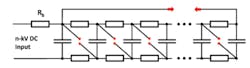
The Marx Generator (Fig. 3) is deceptively simple. When a reasonably high DC voltage is applied to the input, the first capacitor charges through Rb until the potential across it is equal to the input voltage. As it charges, so too do the rest of the capacitors, but more slowly because of the additional resistors and capacitors. Typically, all of the Cs have the same value, and all of the Rs are equal.
When all the capacitors are charged, the first spark gap is triggered. This can be done through an external circuit, or the gap can be adjusted to be slightly smaller than the others. When the first gap fires, it places the first and second capacitors in series. This immediately fires the second spark gap because the voltage across it is twice that on one capacitor. Similarly, the second gap firing places the first three capacitors in series, and so on. In Marx terminology, this is the process of “erecting.”
Several techniques exist to enhance the firing speed. For example, placing the gaps next to each other allows ultraviolet light from one that has fired to increase the conductivity of the next one that has not. Sources also refer to various additional circuit elements that simultaneously add voltage to each gap to improve synchronization. At MV levels, it becomes necessary to immerse circuitry in insulating oil, so some other means of triggering the spark gaps must be provided. At lower voltages, avalanche diodes can be used instead of spark gaps. Regardless of the exact mechanism, Marx Generators are at the heart of many high-voltage E1 simulator designs.
References
- Lecklider, T., “Coping with extreme solar storms,” EE-Evaluation Engineering, October 2015, pp. 16-19.
- “Testimony of George H. Baker, Professor Emeritus, James Madison University, Before House Committee of National Security and the House Subcommittee on the interior of the House Committee on Oversight and Government Reform,” May 13, 2015.
- “Addressing Electromagnetic Threats to U. S. Critical Infrastructure,” Jewish Institute for National Security Affairs’ (JINSA’s) Gemunder Center EMP Task Force, September 2015.
- Longmire, C. L., “EMP on Honolulu from the Starfish Event,” excerpted from an invited paper given to The American Physical Society, March 26, 1985, Note 353.
- Van Citters, K. and Butcher, D., “Documentation of the Trestle at Kirtland Air Force Base, New Mexico,” Van Citters: Historical Preservation, prepared under DACA45-01-D-0010, November 2003.
- Reuben, C., “The Atlas-I Trestle at Kirtland Air Force Base,” Notes on the Web, University of New Mexico, 2010.
- Broad, W. J., “Chesapeake Declaring War on Proposed Military Tests,” The New York Times, Aug. 12, 1984.
- Nelson, J. M. et al, “USS Anzio Empress II Trial,” Naval Engineers Journal, Vol. 108, Issue 3, May 1996, pp. 315-333.
- Corbett, B. and Partak, J., “The U. S. Navy’s New Electromagnetic Pulse (EMP) Program: Resurrecting the Capability in a New World,” CHIPS, January-March 2010.
- “EMP Commission,” Right Web, Institute for Policy Studies, Oct. 19, 2009.
- Weisgerber, M., “Pentagon Moves More Communications Gear into Cheyenne Mountain,” Defense One, April 7, 2015.
- “Testimony of Michael Caruso, Director of Government and Specialty Business Development for ETS-Lindgren, Before Subcommittee on National Security and the Subcommittee on the interior of the House Committee on Oversight and Government Reform,” May 13, 2015.
About the Author
Comment About the Article
To join the conversation, and become an exclusive member of Electronic Design, create an account today!

Leaders relevant to this article: