
At least at low frequencies, dynamic loudspeakers present a low resistance load to an amplifier, so it’s important to use heavy gauge wiring for connections. That’s about as far as you can go with this topic before it gets controversial. Two-core “bonded” or “zip-cord” wiring only costs a few dollars, but you can spend $1,500 or more for “audiophile” quality speaker leads. Some of these products actually have a reasonable amount of silver with gold plating, but it’s not the materials that you’re paying for—it’s how they’re put together.
Solid wire
The fundamental problems that speaker cable manufacturers claim to address are wiring inductance, capacitance, and the difference between DC resistance and AC resistance. The magnetic field generated by the current flowing in a wire creates opposing eddy currents, which are a function of frequency. One consequence of this is referred to as the skin effect, which causes the current density near the center of a wire’s cross section to decrease with increasing frequency. At high frequencies, the current is confined to a thin layer on the conductor’s surface.
Many times, that’s as far as the discussion goes—coaxial cables often have a silver-plated inner conductor to ensure the lowest possible surface resistance at RF frequencies. Looked at in greater detail, the current density reduces exponentially, so at one skin depth, it has reduced to 37% of its DC value.
In addition to the skin effect, two current-carrying conductors near each other exhibit a proximity effect: The magnetic field from one conductor forces the current within the other conductor to occupy less of the total cross-sectional area. If the current flows in the same direction in both wires, the current densities will be higher in the portions of the wires farthest from each other. If the currents flow in opposite directions—as they do in speaker wires—the current density is higher where the wires are closest to each other. In each case, the effective cable area is reduced, causing an increase in AC resistance.
Although the skin and proximity effects are well-known limitations at high frequencies, their importance in speaker cables is harder to quantify. At audio frequencies, these effects are very small. Nevertheless, many websites cite changes in the listening experience caused by different speaker cables. It’s important to note that the skin and proximity effects actually change the wire’s resistance independent of any variation in inductance or capacitance that also may occur.
AC impedance up to 50 kHz
A closed form theoretical solution for the AC impedance of a solid round wire is given by the following equation. Ber() and Bei() are called Kelvin functions and are, respectively, the real Bessel function and the imaginary Bessel function.
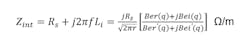
where r = d/2 is the wire radius and Rs is the surface resistivity defined as
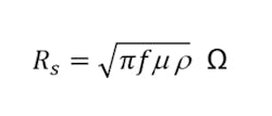
and
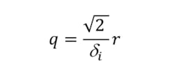
where δi is the skin depth given by
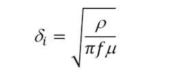
where ρ is the volume resistivity and μ the permeability of the conductor.
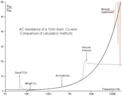
Bessel functions are oscillatory but can be computed with available algorithms. Nevertheless, they are not easy to work with. A recent technical article examines the impedance equation in detail and develops a simplified algebraic approximation that provides very accurate results without involving Bessel functions.1
Courtesy of D. W. Knight
From calculations based on the new formula, Figure 1 shows that AC resistance increases only slightly for frequencies less than 100 kHz. The notes accompanying the diagram refer to various other approaches, which generally have shortcomings near the extremes of frequency or because a truncated series was used in place of the actual function. Using equations developed in reference 1, the greatly expanded curve shown in Figure 2 was calculated for a 1-mm diameter copper wire. It shows a 5% growth in AC resistance at about 27 kHz—2% at 17 kHz.
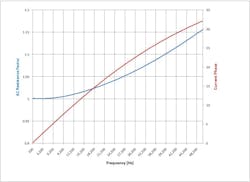
The self-inductance of any diameter of solid wire is about 50 nH/m at low frequencies and falls off very gradually as frequency increases. Taking AC resistance into account, current phase lag for a single wire increases as shown in Figure 2. Of course, a single wire is not used in isolation with the current flowing to ground, so the actual effect of the wire’s self inductance must be considered in combination with the impedance of the speaker being driven and the mutual inductance caused by the proximity of the return lead.
Possible solutions and further effects
Litz wire and strands
The change in AC resistance of a solid wire is small at audio frequencies and usually becomes a problem only at several hundred kHz or a few MHz. Litz wire has been used for many years to overcome the skin effect at these frequencies. Litz wire is constructed from many strands of fine insulated wire that are twisted and woven together so that each strand experiences approximately the same magnetic environment as every other wire in the total bundle. Because the strand diameter often is smaller than the skin depth at the working frequency, very little increase is seen in AC resistance.2 Some manufacturers build speaker cables in a similar way and claim that the construction makes an audible difference.
In practice, loop inductance and the proximity effect may cause larger problems than the skin effect. Two wires must be used to connect an amplifier to a speaker—the output and the return. The distance between the wires determines the loop inductance and also the degree to which the proximity effect is important.
Because each wire is carrying current, the magnetic field from one wire affects the current distribution in the other wire. If the wires are very close to each other, the loop inductance will be reduced but the proximity effect increased. Litz wire minimizes the proximity effect by ensuring that each strand appears in all possible radial and axial positions along its length. This means that although current in a solid wire might be constrained, virtually all the strands of Litz wire will share the total current. Consequently, Litz wire is a good solution to both the skin effect and the proximity effect.
Flexibility is an important consideration, and many cables achieve it by using stranded wire in various configurations. Patent 4,734,544 “Signal cable having an internal dielectric core” describes the cable construction as “… a plurality of bundles of wire strands of conductive material twisted around said dielectric material for collectively carrying positive signal, the wire strands forming each bundle being twisted in a first direction, and the bundles being twisted around said dielectric material in a direction opposite said first direction….”
The wire strands are not insulated. In the inventor’s preferred embodiment, 48 strands of AWG 36 gauge wire are twisted into a bundle with a 1-inch pitch. Six bundles are twisted in the opposite direction with a 3-inch pitch. From wire tables, AWG 36 has a cross-sectional area of 0.0000196 inch2 so 288 strands have an area of 0.00564 inch2—equivalent to between AWG 11 and AWG 12. Twisting the strands and bundles serves to distribute each of the strands in approximately the same way as every other strand—similar to Litz wire. And, using very small diameter wire helps reduce skin effects. Although the dielectric core is mentioned in the patent title, at audio frequencies it appears to have little significance other than providing a form on which the wire bundles can be wound.
Whether or not the strands need to be insulated is dealt with in an IEEE Power Electronics paper. Although the authors do not specify how the wire strands were processed, the premise of the paper is that the resistivity between adjacent uninsulated strands easily can be 1,000x the resistivity of pure copper. So, although the total isolation afforded by Litz wire isn’t achieved, neither is the higher Litz wire cost incurred.3
Tubular conductors
Another construction that has become popular is some form of tubular conductor. Patent 4,954,095 “Cable employing tubular conductors” describes the use of copper tubes, which would, as the inventor correctly claims, eliminate microphony and rectification effects that can be caused by inconsistent contact between adjacent strands in a multistrand/multibundle cable. In the preferred embodiment, a tube with a 0.125-inch outer diameter and a 0.015-inch wall thickness is proposed. The cross-sectional area of such a tube is A = π x (0.06252 – 0.04752) = 0.0052 inch2, similar to the stranded example. For greater flexibility, a 0.010-inch wall thickness also was suggested, giving a total area of 0.0036 inch2, which is between AWG 13 and 14.
A tubular conductor, by definition, cannot support current density except in its annular area. Therefore, its self-inductance is less than that of a solid wire and negligible compared to the mutual inductance associated with a pair of conductors. This invention suggests a 0.4375-inch center-to-center spacing, which results in an inductance per meter of 780 nH. The patent states that because the conductors are spaced apart by more than 2.5x their diameters, “conduction is uniform”—apparently meaning that proximity effects are negligible.
In another example, a type of commercially available speaker cable uses two interwoven layers of helically and oppositely wound silver-plated copper wire to approximate a tubular conductor—similar to the interweaving used to form the outer conductor of a coaxial cable. The individual strands are not insulated but their diameter is sufficiently small to minimize skin-effect problems at high frequencies—the reason that the manufacturer stresses that only two layers are used. The tubular conductor diameter must be large enough that all the cross-sectional wire area adds to about 0.005 inch2—high-quality speaker cables generally seem to have approximately the same area as AWG 12 solid wire.
Weaving the individual strands as described approximates the uniform distribution of Litz wire and should minimize the proximity effect. However, silver oxidizes and could exhibit small rectification and contact inconsistencies similar to those claimed for uninsulated stranded copper wire. Two of these tubular conductors are required, so the cable inductance will be dominated by the loop inductance of the pair.
Yet other sources discuss the use of a coaxial cable to drive a speaker. Typically, such a cable is not being used as a terminated transmission line. If it were, for example if a speaker had a built-in termination and a closely connected amplifier, then the cable could be considered virtually perfect at audio frequencies. The cable’s power-handling capability wouldn’t be an issue so a very small diameter center conductor would eliminate AC resistance issues caused by skin effect. And, because the cable was terminated in its characteristic impedance, capacitance and inductance wouldn’t be relevant.
When coax is used without a termination, the usual formulas for capacitance and inductance still apply, assuming that the drive to the speaker is applied to the center wire and the return from the speaker is on the cable’s outer conductor. It’s important to recognize that the electric and magnetic fields are zero outside of the cable because the currents in the two conductors are equal and opposite.
What happens if two coax cables are used with an amplifier that has a differential output? In this case, the drive to the speaker is balanced, but the coaxial cables act like shielded wires. The current in the outer braid isn’t directly related to that in the center conductor, so the magnetic field created by the inner conductor current is not cancelled outside of the cable. The grounded outer conductor makes a good electric field shield but has little effect on the magnetic field. As a result, loop inductance between the two center conductors exists in the same way as for two ordinary conductors.
Using two coaxial cables differentially may not be as effective as much lower cost twisted pair wiring. Shielded or unshielded twisted pairs allow very good cancellation of external noise because the noise equally affects both conductors. If a twisted pair is used in a differential system, the common-mode signal can be removed. Nevertheless, given the low impedance of dynamic speakers, audible noise problems generally will have originated in more sensitive circuitry well ahead of the speaker cable.
As a final example, one source of AWG 12 two-wire cable (not twisted) describes each conductor as having 67 strands of AWG 30 wire and a finished size of 0.16 inch x 0.33 inch. From wire tables, AWG 30 has a cross-sectional area of 0.0000789 inch2 so the area of 67 strands is 0.0053 inch2, corresponding to AWG 12. Because the cable is stranded, the equivalent conductor diameter will be larger than the 0.081 inch listed for solid AWG 12, such as 0.09 inch. Then the wire radius is 0.045 inch and the spacing 0.24 inch, giving an inductance per meter of 670 nH.
Summary
How reproduced audio sounds is very much a personal experience. Certainly, there are characteristics generally agreed to make music sound more or less like the original performance that are easy to measure. For example, if the bass or treble frequencies have been boosted out of proportion, most people would notice these large effects.
The difference that a specially manufactured speaker cable can have compared to cheap, two-core wire becomes appreciable only at high audio frequencies. That’s not to say that it can’t alter what you hear, but the change it may make at 10 kHz is very small and reduces even further at lower frequencies.
If you can clearly hear high-frequency sounds, “high-quality” speaker cables can be added to your wish list, but they should be somewhere below a better amplifier and more responsive speakers. The cable is just one part of the overall audio system and can’t make up for deficiencies in other components.
References
- Knight, D. W., “Practical continuous functions for the internal impedance of solid cylindrical conductors,” April 2016.
- “Pioneering in Litz for H.F. magnetic windings,” New England Wire Technologies, 2008.
- Tang, X., and Sullivan, C. R., “Stranded Wire With Uninsulated Strands as a Low-Cost Alternative to Litz Wire,” IEEE Power Electronics Specialists Conference, June 2003.
About the Author

Tom Lecklider
Comment About the Article
To join the conversation, and become an exclusive member of Electronic Design, create an account today!

Leaders relevant to this article: