EMP Measurements: Nonnuclear Electromagnetic Pulse Generation
Following the unexpectedly far-reaching and damaging effects observed during the Starfish Prime nuclear experiment in 1962, electromagnetic pulse (EMP) and especially high-altitude EMP (HEMP) have been topics of interest. The necessity to minimize the HEMP threat and show potential enemies that it was being addressed led the military to develop a succession of large HEMP simulators as described in a 2015 EE-Evaluation Engineering article.1
Fast forward several years and the generation of EMP without nuclear explosions or massive investments in infrastructure has become commonplace. This capability is being developed by several countries as so-called directed-energy weapons.
A 2009 paper comments, “At present, a high intensity EMP can be successfully generated without using nuclear weapons. This fact is very significant, especially for applications in the electronic warfare area. It is this aspect of the EMP effect which is of military significance, as it can result in irreversible damage to a wide range of electrical and electronic equipment, particularly computers and radio or radar receivers.”2
A large amount of EMP-related information is available, but one of the more accessible sources is Thomas Holt’s 2002 MSEE thesis titled “Explosively-driven helical magneto-cumulative generators [HMCG].”3 HMCGs are a very practical way to generate an EMP. The well-organized document provides a good discussion of the various factors affecting HMCG performance. Literally, there are lots of moving parts in one of these generators, so clarity is important when describing the various interactions. The thesis also includes detailed discussions of the measurements that were made to evaluate experimental HMCGs and the types of sensors that were used.
HMCG background and operation
Holt comments and his references confirm that, “… the use of chemical explosives to rapidly compress magnetic flux occupying a certain volume was proposed in the early 1950s.” So, HMCGs are not new, although optimizing the chemical-electrical-mechanical interactions is far from straightforward. To develop a better theoretical as well as practical understanding of the device, a Multidisciplinary University Research Initiative (MURI) program was established in 1997-98, which identified several HMCG-related research topics to be pursued by a number of universities.
As Holt explains, “The University of Missouri conducted studies on the behavior of the expanding armature and how cracking on the surface of the metal affects the overall performance of the HMCG. Also … the University of Texas conducted numerical simulations of the magnetic field and current in HMCGs, and Texas A&M University modeled the behavior of the expanding armature using 2D software and verified the functionality of the crowbar ring.” Holt’s work was done at Texas Tech University’s Center for Pulsed Power and Power Electronics. The MURI was funded by the Director of Defense Research & Engineering and managed by the U.S. Air Force Office of Scientific Research.
Figure 1 shows that an HMCG is a relatively simple device.3 It has two cylindrical and coaxial main parts—the hollow metal armature filled with explosive and the helically wound inductive stator. To operate the generator, a magnetic field is first established between the armature and stator by passing a high current through the series-connected circuit. A pulsed power source is connected between the crowbar ring and the left end of the armature to accomplish this—there is sufficient clearance between the two parts to keep them electrically disconnected. Initially, the circuit is completed through the armature to the load and back through the aluminum end piece to the right-hand end of the helical coil, through the coil, and back to the source via the aluminum crowbar ring.
Used with the author’s permission
Taking into account the stator inductance, the output capacitance of the pulsed source, and the resistance of the armature, stator, and aluminum end piece and crowbar ring, the device can be electrically described as a classical RLC circuit. The large applied voltage pulse will establish a peak current in the stator followed by gradual and possibly oscillatory decay depending on the damping provided by the resistance.
The key to efficient HMCG operation is the timing of the explosive detonation relative to the peak current in the stator. The peak current corresponds to the peak magnetic flux, and it is this flux that is going to be compressed by the high explosive.
When the explosive is detonated, the resulting shock wave propagates both radially and axially. The radially directed force causes the armature to expand. The first thing it contacts is the crowbar ring, short-circuiting the external pulse source and closing the armature-stator circuit. Detonation needs to be timed so that the crowbar operates at the instant the peak flux is achieved.
With the crowbar and the armature in contact, equation 1 describes the circuit.
Most of the time, engineers can assume that inductance is a constant, so when you evaluate dΦ/dt = d(Li)/dt, the L can come outside of the differentiation, and you’re left with the familiar V = L di/dt. However, when L is a function of time, as it is in an HMCG, you have to use the product rule for differentiation, giving V = i dL/dt + L di/dt. This is where the first two terms in equation 1 come from that involve the stator inductance LC. LL in the third term represents the fixed inductance of the load, and R in the last term groups the load resistance together with the other resistances in the circuit.
As the armature expands radially, it eventually contacts the stator. Because the detonation was initiated at the left end, the explosion propagates to the right and causes the armature to contact and short out successive turns of the stator winding as the armature expansion progresses in the axial direction. As this happens, the total flux remains approximately constant, but the stator inductance reduces toward zero. The end result is an extremely large, fast current pulse that can be useful in many applications.
EW is a prime area as described in reference 1 and evidenced by the MURI program’s management and funding sources. Holt also mentions lightning discharge simulations, plasma guns, and laser devices as examples of HMCG applications. In each of these cases, the small physical size and large amount of energy available from an HMCG are attractive. Effectively, HMCGs transform the very high energy density of an explosive into an electrical form. Table 1 demonstrates the large energy-density advantage that explosives have compared to other types of energy storage.4
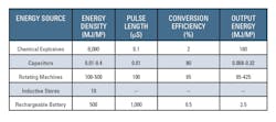
By definition, an explosion occurs in a short period of time. For some of the HMCGs Texas Tech researched, the armature initially contacted the stator about 13 µs after detonation and completed expanding about 16 µs later. As the device name implies, operation is cumulative, which leads to an exponential buildup in output current.
In one test of an HMCG with a tapered stator, the peak current was measured as 78.3 kA and the peak rate of rise as about 50 kA/µs. With an initial “seed” current of 493 A to charge the 52.5-µH stator, the current gain was x159. Also important, the energy gain was x21.9.
Measurements
HMCG research truly emphasizes the meaning of single-shot data acquisition. Although a large amount of work was done using detailed simulations, several physical HMCGs were constructed and operated to provide performance data. Holt notes that an explosion-proof chamber made from ¾-inch stainless steel was used for these tests. After detonation, only shrapnel remains.
During the work at Texas Tech, conducted rather than field quantities were of interest. More broadly, EMP/HEMP research needs to measure rapidly changing fields as well as voltage across or current through a load. So-called B-dot and D-dot sensors are used to measure magnetic and electric fields, respectively, and Rogowski coils often are used to measure current transients.
B-dot, D-dot
Reference 5 was written by six engineers and scientists at the Albuquerque division of EG&G in 1970 with support from Dr. Carl Baum and E. L. Breen of the Air Force Weapons Laboratory. Dr. Baum developed several of the HEMP simulators discussed in reference 1 and later became a key scientist at the Air Force Research Laboratory.
The present version of reference 5, available on the Prodyn Technologies website, includes helpful annotation by Dr. W. Reed Edgel. Prodyn manufactures B-dot and D-dot field probes, and the additional notes help explain the large step from the sensor theory based on Maxwell’s equations to the practical information necessary to use the sensors. Applied Physical Electronics and Montena Technology also manufacture B-dot and D-dot sensors.
From reference 5, the relevant starting point for a magnetic field probe is one of Maxwell’s equations, which states that the curl of the electric field is equal to the partial derivative of the magnetic field with respect to time, or
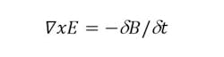
This differential form of the equation can be expressed as
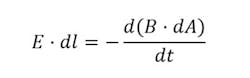
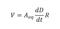
which means that the line integral of the E field around a loop equals the rate of change of the magnetic field through the loop. Because the EMP source and sensor are in fixed locations, B varies only with time, so the voltage measured across a small gap in the loop is given by
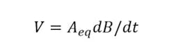
where Aeq is the equivalent sensor area that accounts for the dot product between the B field direction and each element of the sensor surface. The vector dot product is maximized when the B field direction is perpendicular to the probe surface.
The D-dot sensor has a similar derivation to yield
Again, Aeq is the equivalent sensor area, but relative to the electric displacement field D = ε0E where ε0 is the permittivity of free space.
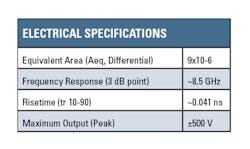
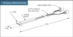
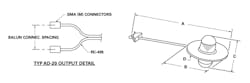
A Prodyn Model B-24 B-dot and a Prodyn Model AD-20(R) D-dot sensor are shown in Figures 2 and 3, respectively. In Figure 2, the small cylindrical sensor actually consists of two isolated D-shaped loops: the upper half of the cylinder and the lower half. The small gaps across which the differential output voltage is developed are located where the strain relief is shown. Each loop drives a separate coaxial cable but the outer conductors are electrically connected to each other.
Courtesy of Prodyn Technologies
The two identical hemispheres of the D-dot sensor in Figure 3 are the differentially connected sensing areas, each insulated from the ground plane on which it is mounted. In both the B-dot and D-dot sensors, no materials are used that can saturate or in some way behave nonlinearly. Sensor calibration is permanent as long as no physical damage has occurred to alter Aeq.
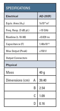
Courtesy of Prodyn Technologies
Rogowski coil
The magnetic field generated by current in a straight wire is circular and surrounds the wire with the field direction given by the right-hand rule: With the wire grasped by your right hand and with your thumb pointing in the direction of the current flow, the B field direction will correspond to the direction in which your fingers point.
A Rogowski coil is a long solenoid that has been formed into a loop around the current-carrying wire, as shown in Figure 4. The B field lines flow through all the turns in the coil, which induces a voltage. Because the coil operates in the same way as a transformer, only changes in flux are sensed. The output voltage can be expressed as
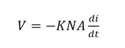
where K is a constant, A is the average area of one turn of the coil, and N is the number of turns. In Holt’s HMCG work, measuring the rate of change of current was necessary, so the output from a Rogowski coil could be used without integration.

Courtesy of Power Electronic Measurements
Many commercial Rogowski coils either include or have an optional integrator, as shown in the figure, so that you can measure current rather than its derivative. Unfortunately, integration degrades overall performance because it affects bandwidth. The bare Rogowski coil has a very wide measurement range and is exceptionally linear because it doesn’t contain any materials that can saturate.
Rogowski coils are commercially available in almost any size and offer the capability to be placed around even very large current-carrying structures without having to break the circuit as would have to be done to insert a current-sensing resistor. They also are very easy and inexpensive to construct. This aspect was important to Holt because the monitoring coil was destroyed each time an HMCG design was tested.
References
- Lecklider, T., “Acknowledging the HEMP threat,” EE-Evaluation Engineering, November 2015, pp. 30-33.
- Dražan, L, and Vrána, R., “Axial Vircator for Electronic Warfare Applications,” Radioengineering—Proceedings of Czech and Slovak Technical Universities, April 2009, pp. 618-626.
- Holt, T. A., “Explosively-driven helical magneto-cumulative generators,” MSEE Thesis, Texas Tech University, August 2002.
- Altgilbers, L.L. et al, Magnetocumulative Generators, Springer-Verlag, New York, 2000.
- Edgel, W. R., “Reproduction and annotation of the EMP sensor application guide,” Prodyn Technologies, 2013.
About the Author

Tom Lecklider
Comment About the Article
To join the conversation, and become an exclusive member of Electronic Design, create an account today!

Leaders relevant to this article: