Optical Modulation: Boosting throughput by adding complexity
In many ways, high-speed optical communications are following the path that wireless technology has blazed. Of course, optical and wireless networks use different technologies to deal with specific physical-layer characteristics. Nevertheless, the basic challenge is how do you increase the amount of information that can be transferred in a given amount of time?
Of the two complementary approaches often used, the first increases the size of the pipe. Where additional channels are available, the data can be distributed among them, which multiplies the data rate per channel by the number of channels. The Link Aggregation Control Protocol supports the aggregation of up to eight copper or optical-fiber channels to increase Ethernet throughput, for example. For LTE-Advanced, carrier aggregation allows up to five 20-MHz channels to be combined to increase bandwidth.
Complex modulation is the second method, and wireless networks have adopted several versions to further increase throughput. The symbol rate doesn’t change, but each symbol carries more information. Quadrature amplitude modulation (QAM) is a popular protocol that encodes information as a combination of amplitude and phase values. The familiar constellation diagram is a graphical representation of the available states—most often 16, 64, or 256, corresponding to four, six, or eight bits per symbol.
Although conveying a large amount of information per symbol obviously is attractive, noise is a limiting factor. LTE uses an adaptive modulation scheme that adjusts the number of bits per symbol depending on the quality of the wireless path, among other factors.
The optical equivalent
A 2008 technical report comments, “In the latest optical transmission system using wavelength division multiplexing, the transmission speed is mainly 10 Gb/s for each optical fiber and wavelength. The speed of 40 Gb/s is expected in the next generation to raise total transmission capacity.”1 The report further notes that phase-shift keying (PSK) and/or differential PSK (DPSK) were introduced to increase throughput to 40 Gb/s. At rates up to 10 Gb/s, on-off keying, a form of direct detection, is a simple and generally satisfactory modulation scheme, but at higher speeds, optical-fiber dispersion and nonlinear effects can cause reading errors.
PSK or DPSK is a coherent modulation method, which means that the receiver must be able to track the signal phase to extract information. This is in contrast to direct detection, which only measures power. An alternative to PSK that is claimed to be a simpler solution is four-level pulse-amplitude modulation (PAM-4). As the name suggests, the data is encoded as four distinct power levels. Like on-off keying, the four levels can be detected without a phase reference.
Instead of adopting 40 Gb/s, recent activity has favored going directly from 10 Gb/s to 100 Gb/s for several reasons. First, the amount of network traffic has rapidly increased, and upgrading to 40 Gb/s would only be an interim solution. Second, coherent systems include a DSP that recovers the encoded amplitude and phase information. As a 2016 white paper notes, “… [The] DSP can compensate for very large chromatic and polarization mode dispersion caused by optical fibers and eliminate the need of optical dispersion compensators and the associated optical amplifiers. This saves not only significant capex, but also simplifies optical network design tremendously because the complicated dispersion map associated with 10G and 40G direct detection systems is no longer needed.”2 Finally, various standards have defined 100-Gb/s schemes, and a range of modulation methods provides a route to ever-higher throughput as system components are improved.
Because light can have two independent orthogonal polarization directions, modulation schemes may include a DP prefix meaning dual polarization. Two separate signals are transmitted, one with vertical and the other with horizontal polarization. PSK modulation shifts the carrier phase independent of polarization so DP-binary phase shift keying (DP-BPSK) encodes two bits of information in each symbol—one bit on each polarization. DP-quadrature phase shift keying (DP-QPSK) uses four phases and encodes four bits. Because the modulations on the two polarizations are independent, there are 16 combinations of the bit states. And, 16QAM encodes four bits of information as combinations of four phases and four amplitudes: DP-16QAM encodes eight bits of information per symbol.
Without using a symbol rate faster than 25 Gsymbols/s, PSK and QAM modulation schemes are facilitating 100-Gb/s systems. Reference 2 discusses opportunities that photonic integrated circuits (PICs) from NeoPhotonics provide for 400 Gb/s. The reference states that DACs and ADCs with high ENOB values are needed to implement QAM systems beyond 16QAM. Those components are not yet available, so the paper concludes that “… most companies will use a high baud rate rather than a high constellation. For example, a single wavelength of 56-64 Gbaud/DP-16QAM can offer a total capacity of 448-512 Gb/s.” Baud rate is equivalent to symbol rate.
As speeds increase, the role of the DSP also becomes more essential for correct link operation. The optical fibers typically used in communications networks do not preserve the polarization state. As a recent article notes, “The polarization directions evolve along the signal’s way through the fiber so that the state of polarization at the end is not simply related to the orientation of the receiver…. All the degrading effects that happen to the fully polarized light in the fiber channel can be mathematically described with a so-called Jones matrix…. So, we basically need to find the Jones matrix to deduce the original signal from the measured received signal.”3
Transmission
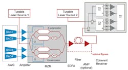
Speed is one part of the 100-Gb/s equation. And, for coherent approaches, providing multiple time-aligned channels is another. Because data is characterized by its I and Q components, four separate bit streams are required to drive Mach-Zehnder I/Q optical modulators for both polarizations, as shown in Figure 1.
Courtesy of Keysight Technologies
An arbitrary waveform generator (AWG) can be a good source of baseband I/Q modulation signals. As the datasheet for the Tektronix OM4200 Optical Modulation Analyzer discusses, “The AWG70000 Series AWGs and the PPG3000 Series Programmable Pattern Generators offer the flexibility to choose the type of signal generation instrument suited to the test requirements. The AWG70000 Series can reach sampling rates as high as 50 GSa/s with 10 bits vertical resolution.… The arbitrary waveform generation capabilities of the AWG70000 Series make it possible to create multilevel signals such as 16QAM or 64QAM, add impairments to a signal, or create waveforms that are precompensated for the real-world effects of the test system.”
The datasheet continues, “[The] PPG3000 Series can generate patterns up to 32 Gb/s and offers 1, 2, or 4 channels in a single instrument. The patterns can be standard [pseudo-random binary sequence (PRBS)] patterns or user-defined. Using a 4-channel pattern generator makes creating dual-polarization I-Q waveforms very simple.”
A single two-channel AWG70002 is specified to have up to 5-ps skew between channels before correction. The output skew control has a range of ±100 ps with a 500-fs resolution. Considering the need for simultaneous I/Q generation in two polarizations, the four-channel PPG3204 is the better solution although it is limited to pulse waveforms and is not as fast as the AWG70000. The skew adjustment range among the four channels is ±25 ps with 100-fs resolution.
Keysight Technologies also offers a high-speed multichannel AWG, the 65-GSa/s M8195A with up to four channels. As described in the product’s datasheet, “Since all 4 channels are generated by the same instrument without any external circuitry, precise synchronization down to the femto-second-range can be achieved and maintained…. The M8195A uses digital predistortion techniques for frequency- and phase-response compensation of the AWG output and any external circuits. These are required in order to achieve a clean signal at the device under test…. Distortions generated by cables, amplifiers, etc. can also be compensated by embedding/de-embedding the S-parameters of the respective circuits or by performing an in-situ calibration using Keysight 81195A Optical Modulation Generator software.”
Channel-to-channel skew is adjustable within a ±50-ps range with 10-fs resolution. In addition, all four channels can be delayed up to 10 ns with 50-fs resolution. Output amplitude is specified as 1-V single-ended into 50 Ω or 2-V differential—the same as Tek’s PPG3204 with the ADJ Amplitude option.
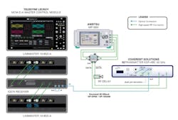
At the Optical Fiber Communications Conference and Exposition (OFC) held this year in Anaheim, CA, Anritsu, Teledyne LeCroy, Coherent Solutions, and Oclaro demonstrated equipment that can achieve a 400-Gb/s data rate, as shown in Figure 2 from a press release. The symbol rate was 56 Gbaud with an overall bit rate of 448 Gb/s resulting from
DP-16QAM modulation.
Courtesy of Teledyne LeCroy
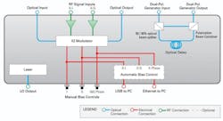
Coherent Solutions’ IQTransmitter features automatic modulator bias control and is available in full dual polarization (FDP) and emulated dual polarization (EDP) versions. Both models have Oclaro’s latest LiNbO3 Mach-Zehnder modulators and provide linear RF amplifiers to drive them—four of each for the FDP and two of each for the EDP. An internal laser source is included as well as an input for an external source. As described on the company’s website, “The [EDP] can generate dual-polarization phase-modulated signals by optically polarization multiplexing a delayed copy of the single-polarization modulated signal.” To accomplish this, the EDP adds a 50/50 beam splitter, an optical delay, and a polarization beam combiner, as shown in Figure 3.
Courtesy of Coherent Solutions
Please note that Figure 2 incorrectly labels a couple of ports. The “LO In” and “LO Out” labels are correct (Laser In and Laser Out on the actual instrument), but “out” shown next to the LO out label should read “in” (Signal In), and the “in” label next to the LO in label should read “out” (Signal Out). The internal laser is being applied to the EDP single polarization modulator in the upper section of the IQTransmitter. The modulated signal is output from the upper section and applied to the lower section to simulate a second data stream with orthogonal polarization. The final output from the polarization beam combiner in the lower section is the emulated dual-polarization signal. The ports are shown clearly and correctly labeled in Figure 3.
To understand what the four companies demonstrated, you have to appreciate that they only showed 400-Gb/s feasibility—the test setup did not have the flexibility that a four-channel 56-Gb/s AWG or pulse generator would give.
Anritsu’s MP1800A Signal Quality Analyzer measures bit-error-rate (BER) up to 32.1 Gb/s and is available in a two-channel version. Although the term analyzer implies that some characteristic of an input signal is being measured, to quantify BER, an analyzer must control the stimulus signal driving the DUT. For the OFC demonstration, the MP1800A was used as a signal generator with two 28-Gb/s outputs and their complements.
The outputs drive the 2:1 multiplexer inputs on Anritsu’s G0361A 2-bit DAC, resulting in a 56-Gb/s PAM-4 differential output. The G0361A DAC also was driven by a 28-GHz clock to control the multiplexer, but this connection is not shown in Figure 2.
The two single-ended sides of the DAC’s differential four-level output drive the I and Q RF signal inputs on the EDP IQTransmitter—so even with single polarization, the I data and the Q data are constrained to be closely related. The EDP transmitter simulates dual polarization by creating a delayed version of the basic signal so the data transmitted on the second polarization direction is not independent of the data in the first direction. Nevertheless, the final output is a DP-16QAM signal running at 8 x 56 = 448 Gb/s. While showing feasibility, the demonstration simply didn’t exercise all of the 256 possible states in the same random manner possible with a 56-GS/s four-output AWG or pulse generator.
The Model OM5110 is a 46-Gbaud dual-polarization optical transmitter from Tektronix. Similar to Coherent Solutions’ FDP IQTransmitter, the OM5110 includes a laser source—either C- or L-band—together with the necessary Mach-Zehnder modulators and optical splitter and combiner, amplifiers, bias circuitry, and control electronics. Tek also offers external lasers such as the OM2012 Tuneable Laser Source that can be used instead of the internal laser.
Reception/analysis
Coherent demodulation requires phase information, which implies the need for a local oscillator—in this case, another laser. By taking advantage of DSP capabilities, an intradyne system can be implemented rather than a technically more difficult heterodyne approach. This is important because an intradyne system uses a free-running laser rather than one having a fixed offset from the transmitter laser’s frequency.
As described in a 2010 article, “Coherent measurements require a phase reference from the original signal (homodyne), a frequency-offset reference sufficient to fully separate the down-converted spectra (heterodyne), or from a free-running, but similar-frequency independent source. This introdyne method relies on real-time capture and digitizing of the difference-frequency waveform, whose bandwidth is the modulation bandwidth plus the difference frequency. Carrier phase recovery is performed by a software phase-locked loop—removing the frequency difference between the signal and phase difference, then applying a Wiener filter to predict the phase trajectory of the signal….”4
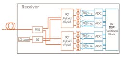
Real-time capture of very high bit-rate signals only has become possible because of recent speed improvements in DSOs. For example, a technical paper5 on the Teledyne LeCroy website describes an experiment to recover coherent modulation from a 56-Gbaud 224-Gb/s QPSK signal. Oscilloscope performance at the time was only just adequate. As the authors note, “… the 80-GSamples/s ADCs oversample the 56-GBaud signals by only a factor of 1.4. Since the oscilloscope front end acts as an anti-aliasing filter that limits the signal spectrum to <30 GHz, sampling at >60 GSamples/s satisfies Nyquist’s criterion.”Figure 4 shows a block diagram of a coherent receiver from Infinera. As described in a white paper,6 “The incoming optical signal passes through a polarization beam splitter, which divides the signal into two orthogonal polarization signals. One of these signals now consists of the X-polarized component, and the other consists of the Y-polarized component. Each component is now passed into a 90-degree optical hybrid circuit. Each optical hybrid consists of a 2×2 optical coupler with a 90-degree phase delay function implemented on one arm of the coupler. This circuit allows the I and Q phase components of the signal to be extracted as a result of the interference generated by the local oscillator.”
Courtesy of Infinera
After detection by photodiodes and amplification in transimpedance amplifiers, a fast DSO often is used to digitize the four signals—horizontal I and Q and vertical I and Q. As discussed in reference 3, however, these four signals are not simply related to those that were transmitted. Specialized algorithms executed by the DSP are key to recovering the original data.
LeCroy provides coherent optical receivers for three baud rates: 25 GHz IQS25, 42 GHz IQS42, and 70 GHz IQS70. Recommended scopes are the company’s 25-GHz 10-25Zi-A, the 36-GHz 10-36Zi-A, and the 65-GHz 10-65ZiA, respectively. As LeCroy’s Optical Modulation Analyzer Systems brochure describes, “Optical-LinQ … runs entirely within the user interface of the 10Zi-A…. Optical LinQ provides fully automated control of the IQS receiver, phase recovery algorithms, polarization demultiplexing, as well as an exhaustive number of modulation displays and parameters.”
Further, according to the brochure, the software application “… comes with preset support for many common optical modulation formats, including QPSK, 16QAM, and 64QAM. If you are developing or working with nonconventional modulation formats, you can define your own format using Optical LinQ’s powerful custom modulation format definition capability.”
Keysight has positioned the integrated 63-GSa/s and 23-GHz bandwidth N4392A Optical Modulation Analyzer as the direct match to the 65-GSa/s M8195A AWG. The N4392A includes all of the elements in Figure 4 but as options so that you can configure the unit to suit your application. For example, the full-featured configuration with all analysis and test capabilities comprises these options:
- 300—23-GHz optical receiver including optical coherent receiver digitizer and local oscillator,
- 310—23-GHz electrical receiver including electrical receiver without any optical components,
- 320—extended local oscillator and source package adding the auxiliary source and local oscillator external input and output,
- 410—additional optical modulations format software package,
- 420—user-configurable OFDM decoder, and
- 430—ICR characterization software.
As described in Reference 7, the manufacturer’s Model 4391A “… is for more advanced applications. Here, the ADCs of a [Z- or X-Series Infiniium scope] are used. They provide sample rates up to 80 GSa/s simultaneously on all four channels allowing the analysis of optical signals with up to 62.5 GHz. Higher sample rates of 160 GSa/s with analysis bandwidths of 125 GHz are available optionally … for simultaneous analysis of super-channel signals….” Like the N4391A, the N4392A includes the 89601B vector signal analysis software extended for optical requirements.
Tek’s OM4000 Coherent Lightwave Signal Analyzer also uses a separate high-speed oscilloscope following signal detection in a coherent optical receiver. According to information on the company’s website, “The OM4245 Coherent Optical Modulation Analyzer … [is] tightly integrated with the DP070000SX Series 70-GHz real-time oscilloscopes and the DSA8300 Series 70-GHz equivalent-time oscilloscope.
“The OM4245 uses coherent detection to acquire fiber signals carrying up to 80 GBaud, then analyzes both modulation and source properties using the power of optical-industry-tested DSP. It presents … results and graphical plots with the ease of use offered by a dedicated graphical user interface. Dynamic … MATLAB integration provides … analysis system customization and extensibility.”
EXFO’s PSO-200 Optical Modulation Analyzer with 60-GHz bandwidth takes a different approach. Rather than directly convert the modulated optical signal to an electrical one via a fast photodiode and transimpedance amplifier, the PSO-200 uses optical sampling. Key to the technique is highly nonlinear optical fiber that acts as a mixer between the optical signal and a very narrow optical pulse.
In traditional dense wavelength multiplexed transmission systems, fiber nonlinearity can cause so-called four-wave mixing, which, as the name suggests, is comparable to intermodulation distortion caused in electrical communications systems.
EXFO has exaggerated the effect in a specially designed fiber to create an idler wave that “… contains an amount of power proportional to the signal power sampled during the … short [pulse] time duration. This idler wave can subsequently be spectrally filtered to isolate it from residual pump and signal light, and the detected photo current then will consist of a string of spikes at a repetition rate determined by the pulse source, such as 100 MHz.”8 The size of the spikes is proportional to the optical signal level.
As discussed in reference 8 as well as in the PSO-200 datasheet, a very fast optical gate is followed by a relatively slow photodiode. Although the datasheet states that the instrument is suitable for analysis of random data in constellation or eye diagram modes, the PSO-200 is best suited to repetitive data such as PRBS patterns at rates up to at least 100 Gb/s.
The future
High-speed optical communications are already achieving 100 Gb/s for many links. The technology works—whatever the proprietary technology details may be. Some of the speed advances have come via the network operators such as Ciena with its WaveLogic 3 and WaveLogic 3 Extreme. According to the company’s website, “WaveLogic Photonics is Ciena’s fully instrumented, intelligent photonic system comprising WaveLogic coherent optics and flexible line elements that combine with embedded and discrete software tools to offer superior automation, control, and visibility of optical networks.”
NEC, Inphi, and Finisar also have been active, but primarily in developing network elements such as pluggable coherent transceivers. The pluggable qualifier immediately sets a size constraint and implies that a great deal of optical and electronic circuit integration is required. NeoPhotonics, Oclaro, and OptoPlex, among others have executed PICs that facilitate highly integrated optical network elements.
The 100-Gb/s components and systems operational today are just the beginning, with vendors already demonstrating 400- and 500-Gb/s feasibility.
References
- Kazunori, T., et al, NX7000 Optical Phase-modulation Analyzer—Real-Time Simultaneous Measurement of Modulated Phase Distribution and Demodulated Waveform, Yokogawa, Technical Report No. 46, 2008.
- “Photonic IC Enabled Coherent Optical Systems,” NeoPhotonics, October 2016.
- Michel, S., “Coherent optical receivers—the complete answer,” Lightwave, Sept. 18, 2014.
- van der Weide, D., “Measuring complex optical modulation in fiber,” Lightwave, Feb. 1, 2010.
- Winzer, P. J., et al, “56-Gbaud PDM-QPSK: Coherent Detection and 2,500-km Transmission,” Teledyne LeCroy, 2011.
- Coherent WDM Technologies, Infinera, White Paper, 2016.
- Characterizing High-Speed Coherent Optical Transmission Systems,” Keysight Technologies, Part 1: generating clean modulated signals using the M8195A 65 GSa/s AWG, Keysight Technologies, Application Note, 2014.
- Andrekson, P. A., “Optical Phase-Sensitive Sampling to Capture Optical Waveforms,” EE-Evaluation Engineering, Communications Test Report, June 2010.
For more information
About the Author


