Finding effective strategies for instrument-to-DUT interfacing
Switching is a key aspect of any automated test system, enabling efficient sharing of test resources with devices under test. The concept is straightforward, but there are many subtle factors to take into consideration when choosing and applying switching systems.
Bob Stasonis, sales and marketing director at Pickering Interfaces, cautioned, “Switching can be more of a black art than one would think, especially as signal frequencies increase, as there is more to switching than meets the eye.” To help, Pickering employs support engineers with many years of functional-test experience, he said, adding that the company’s online knowledgebase (pickeringtest.com/kb) has answers to most ATE questions on switching and simulation.
Time to market is always critical, Stasonis said, and is becoming even more so. “The time it takes to design, integrate, and deploy test systems is crucial,” he said. “Regarding switching, the lengthiest operations include switch-module selection, cabling the module, and test programming—all of them have a cost.” He said Pickering’s selection of switching modules, quick turnaround of orders on its flexible assembly lines, and the availability of compliant drivers and other software tools assure test engineers that Pickering can and will help minimize test integration bottlenecks.
Selecting the right switch for your application also presents challenges. “In the almost 30 years that Pickering has been designing and building switching systems, we still find new applications that cannot be addressed by commercially available switching solutions,” Stasonis said. “This is one of the reasons we have so many options in our catalog. When a company comes to us for help, we are more open to designing new products to support its applications. So, if the customer’s requirements have the potential of being accepted by the industry, we will create a new design and add it to our catalog.”
Cytec’s application guide (http://cytec-ate.com/appguide.html) hints at the plethora of choices you face when selecting switches. Top-level selections in the guide let you choose signal type, test type, configuration, and connector type. Subcategories include instrument type (from spectrum analyzer to hi-pot tester), communications application type (from RS-232 to satellite and fiber optics), configuration (for example, 1xN multiplexer or NxM matrix), and connector type (from coax to screw terminals). The company says it supports signals ranging from DC to 40 GHz at levels from microvolts to 25 kV and femtoamps to 100 A. It offers discrete relays as well as matrices and multiplexers. Specific products include the CXAR Series DC to 2-GHz coax systems and the HX Series high-voltage systems. The company will also build custom systems, commenting that nearly half its shipped products are not listed in its brochures.
Norton W. Alderson, vice president of marketing at Universal Switching Corp., commented, “It seems that the biggest challenge is hardware budgets. Clients are trying to do more and more with smaller budgets. To help address this, three of our latest products have been designed from the ground up for lower cost and for smaller rack space (1RU).”
Alderson continued, “For many high-frequency applications, another challenge is the actual length of signal cabling needed to connect to a switch. Even with the best of cables, there can be significant signal loss.”
And Mike Dewey, director of marketing at Marvin Test Solutions, commented, “With the ongoing trend to use card-modular architectures and specifically PXI for ATE systems, customers are continually challenged with channel density and implementing reliable interconnects to their test system interface (receiver).”
Switching products
Companies offer a range of products to help implement effective switching strategies. “USC has introduced four unique client-application-driven product lines within the last six months,” said Alderson. “Some are ATE focused, and others are more focused within the communications industry,” targeting government clients, satellite ground stations, teleport providers, and laboratory and university research programs.
“Our advanced System UC1 is a modular 1RU sized unit, which is resilient and has robust features and capabilities,” said Alderson. “It’s the culmination of USC’s 25 years of switching design experience fused with the latest in component and design capability.” System UC1 (Figure 1) delivers space for one double-wide or one or two single-wide “PUC” elements that are installed at the rear, he explained. To date, the product line offers PUC elements for multiple 1xN (1×2, 1×4, and 1×6) switching sections and spanning frequencies of DC to 6 GHz, 18 GHz, 26 GHz, or 40 GHz. “A unique feature is that a PUC can be removed from the chassis and remotely located,” Alderson said. “This might be useful in test applications where you would want to move the switching right next to an item being tested to keep test cables short. PUC extension cables are available up to 400 feet.”
Also new is the System RSX4 modular 1RU-sized unit, which is designed for ultrahigh-reliability redundancy (A/B) switching. It accommodates one or two single-wide PUC redundancy elements, each of which can be populated with one or two A/B sections. “The RSX4 is different from our UC1 as it is designed exactly for redundancy (A/B) switching, and not 1xN or MxN switching,” Alderson said. “They were designed at the same time,” he added, but noted that the RSX4 includes an illuminated front-panel control and display with four buttons, redundant power supplies, dual AC inputs, a web-browser interface, a 10/100 Ethernet port, an LXI-certified C3-Lite controller, a multiserial port (RS-232C/422A/485), and an alarm port with hard contact.
Still another new product from USC is the modular 1RU-sized MDU4 signal-distribution system—a companion product used in many applications with switching systems. “Its singular purpose is to deliver low-cost high-reliability distribution of analog and digital signals,” Alderson said. “It’s intended to be either rack-mounted or benchtop, used within an R&D environment. The MDU4 chassis provides four slots, which can be populated with a mix of distribution elements. It has dual (redundant) power supplies with dual AC inputs and has built-in power supply monitoring with LED health indicators and audible fault alarm.”
Finally, USC recently debuted the 6RU-sized SLM32 modular 32×32 switch matrix, designed for resilient operation in a matrix format up to a 32×32, with support for frequencies up to 3 GHz. “Each input and output is served by an individual hot-swap element, so should a failure occur, it will only affect the individual input or output that it serves,” Alderson said. In addition, an initial smaller configuration can easily be expanded in the field by having the user add more input or output elements. User connectivity is at the rear with a choice of SMA or BNC connectors independent of the I/O elements, so signal cables needn’t be touched. “This unit was originally designed for routing satellite L-band signals, providing single-port-increment expansion capability and failure safeguards,” Alderson said, “but it has similar applications in the automated-test industry as well.”
Focus on density
Stasonis at Pickering Interfaces outlined several application areas the company serves, and the unique requirements of each—for example, defense and aerospace customers need products that are available for a very long time. “We commit to keeping products in our catalog for 15 to 20 years and beyond—we still sell and support our GPIB-based switching systems that were designed almost 30 years ago,” he said. “The migration of older obsolete VXI test systems to PXI-based test systems is very important to our military. This is why we have created a cross-reference on our website from popular VXI switching modules to Pickering PXI products.”
Stasonis said that semiconductor applications require high relay closures and fast switching times, while RF and microwave applications require accuracy and repeatability as well as long service life. Finally, he said, “Automotive ECU manufacturers basically need everything: high-power switching for 12- and 24-V applications, high voltage switching for electric/hybrid vehicles, and impedance-controlled switching for network testing.”
Some recently introduced switching products include the BRIC PXI Switch Matrix family (Model 40-559), in which the company incorporated sibling company Pickering Electronics’ Series 120 4-mm by 4-mm 1-A reed relays. “This design has allowed us to effectively double the number of 1-A crosspoints in any of our 2-, 4-, or 8-slot BRIC models and provide our customers more robust switching for demanding applications,” he said.
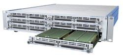
In addition to the BRIC design, Pickering Interfaces recently introduced its Model 65-2xx LXI Scalable Matrix platform (Figure 2). “This platform gives us many advantages,” Stasonis said. “First, the size of the circuit boards in the 65-2xx is much larger than in 3U PXI, enabling Pickering’s engineers to create much larger matrices with minimal cabling. Second, the platform has a much greater DC power capacity than a standard PXI chassis, allowing it to be implemented in applications requiring a large number of relays to be closed simultaneously. This is a major advantage in the semiconductor industry. In addition, our hardware-triggered sequencer allows for very fast switch times, eliminating any latency issues in the network that could slow the test.”
A new product line for Pickering Interfaces is a family of USB/LXI switching chassis, now including the 2-slot Model 60-104 and 4-slot Model 60-1054. “These chassis can utilize virtually all of Pickering’s 1,000-plus PXI switch and simulation modules,” Stasonis said. “They provide a low-cost means to locate the necessary switching closer to the unit under test.”
Functional test focus
Marvin Test Solutions is continuing to invest in and expand its portfolio of PXI products for switching applications with a focus on board- and system-level functional test, Dewey said. “These applications can require a range of capabilities including high-density switching, high-current capability, and RF/microwave switching,” he added.
Dewey continued, “By offering both 3U and 6U products as well as the PXI-based GENASYS switching architecture, we have been able to help customers optimize their systems for both switching density and size,” he said. “Additionally, we offer switching products that combine high-current switching functions with relay matrices, allowing customers to optimize their system configuration as well as economize on slot count. The GENASYS architecture and associated switch cards, based on the 6U PXI standard, can support over 4,000 interface test points, eliminating thousands of interconnecting wires and offering superior signal integrity, switching flexibility, and system reliability.” An alternative approach with multiple PXI cards, he added, would require intermodule cabling as well as cabling to the test interface, compromising signal performance and maintainability.
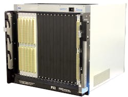
Dewey elaborated on the GENASYS platform (Figure 3), saying it offers test engineers a PXI-based, high-density switching subsystem that incorporates the MAC Panel SCOUT cable-less receiver interface, eliminating thousands of wired connections for high-density I/O applications. “For those customers that need to transition from proprietary legacy ATE systems, the GENASYS platform is an ideal solution for addressing the complex switching requirements as well as offering the open architecture flexibility of PXI,” he said.
ATE platform
Astronics Test Systems, having purchased the ASCOR ATE Signal Switching product line from Giga-tronics in June 2016, offers what was originally named the ASCOR GT-4600 universal switching system, which the company described as an ATE platform rather than a box of switches. A 2014 Autotestcon paper written by Robert C. Waldeck, then vice president, business development, switching, at Gig-tronics ASCOR, and Robert W. Dahl, technical project manager, systems and strategies, at Rockwell Collins, described the implementation and use of the 4600.
Some issues that led to the development of the 4600 were outlined in a Gigi-tronics publication from 2012 written by Waldeck. For example, if you insert a switch in a cable connecting your instruments to your DUTs, then electrically, the switch becomes part of the cable. Waldeck wrote, “If you remember nothing else about this white paper, remember this one thing. The switching system becomes part of the circuit. If you have a nice, balanced 50-Ω coaxial connection between the source and the DUT, and then need to impose a switch in the middle, make sure it does as little as possible to upset the nice 50-Ω balanced circuit.”1 Suggestions include keeping paths as direct and as short as possible, eliminating stubs, matching conductor types as closely as possible to the DUT, and selecting switches that match the conductor type, and minimizing impedance discontinuities caused by mixing wire types.
The 2014 Autotestcon paper elaborated on cabling issues. Waldeck and Dahl noted that engineers can spend many hours choosing switch cards and designing the cables. Then, wiring up switches often leads to interwoven cables at the DUT interface, which often require parameter characterization and which degrade over time. Further, maintenance performed on one signal wire often causes collateral damage. As an alternative that would reduce development time and reduce diagnostic and maintenance costs over the life of the ATE system, the authors proposed the concept of the “ATE transmission”—a switching instrument that employs a software-defined ATE I/O map to route ATE resources directly to the DUT.
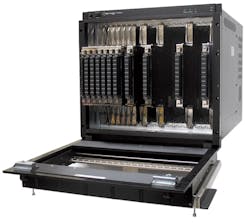
The GT-4600 system (Figure 4) is based on a 21-slot chassis with a selection of switch cards and accessories. A switched bus with a passive backplane enables stubless connections between any two cards in the system. Cards extend to the test receiver, eliminating the cables and associated hassles.
In the Autotestcon paper, Waldeck and Dahl described the GT-4600 as “…a next-generation switching system specifically designed for ATE applications. The GT-4600 combines all of the best elements of existing switching systems and integrates them into a single, state-of-the-art platform. The GT-4600 provides optimal performance while dramatically simplifying the process of designing, building, and maintaining an automated test system.”2
Conclusion
Moving ahead, Dewey at Marvin Test Solutions said, “At MTS, we are really focused on delivering purpose-built products—those products that address a customer’s needs, based on specific functional test requirements.” Those products may be derivatives of existing products or new products, including multifunction switch products that offer capabilities such as high-current switching or multipole switching, he said.
Pickering Interfaces is focusing on improving switching density, supporting higher bandwidths and voltages, and offering more choice, Stasonis said. “In addition, we are working to create a complete ‘environment’ for our switching and simulation products,” he added. This environment includes tools that make it easier to select the right switching module, fast deliveries, a range of connectivity products to simplify integration, software drivers compatible with all popular programming environments, and software that simplifies test-program development.
USC will continue development of its UC1 and RSX4 platforms by introducing more PUC elements, including double-sized versions, that include digital, relay, and solid-state technologies. “We feel this is important to try to offer clients the best balance between value and performance with advanced features,” Alderson said.
“For the satellite and communication industry, to enhance the capabilities of our SLM32 matrix, USC will also be introducing a unique single-channel RFOF (RF Over Fiber) receiver we are calling the FiberSTIK,” Alderson continued. “This compact device converts an RF fiber input to analog RF. You simply install the FiberSTIK on an input connector and that is it. It receives its DC power from the switching system via the input connector if the system has the LNB power option. It is intended for L-band signals; however, it will provide a frequency bandpass of 50 MHz to 5 GHz.”
References
- Waldeck, Robert, “Improved Switching Architectures for ATE Systems,” Application Note, Giga-tronics, 2012. http://www.gigatronics.com/uploads/document/AN-GT150A-Switching-Architecture-for-ATE-Systems.pdf
- Waldeck, Robert C., and Dahl, Robert W., “A next generation ATE switching solution: As applied by Rockwell Collins,” Proceedings of Autotestcon 2014, Sept. 15-18, 2014. http://ieeexplore.ieee.org/document/6935127/
About the Author

Rick Nelson
Contributing Editor
Rick is currently Contributing Technical Editor. He was Executive Editor for EE in 2011-2018. Previously he served on several publications, including EDN and Vision Systems Design, and has received awards for signed editorials from the American Society of Business Publication Editors. He began as a design engineer at General Electric and Litton Industries and earned a BSEE degree from Penn State.


