Automotive Power-Conditioning Circuit Eliminates Power-Hold Relay

>> Electronic Design Resources
.. >> Library: Article Series
.. .. >> Series: Ideas for Design
.. .. .. >> Ideas for Design Vol. 1
Download this article as a PDF file
Automotive electronic control applications require robust input power conditioning. The circuitry must absorb 100-V transients on one hand, while providing a stable dc bus for a few hundred milliseconds after the ignition is switched off, so the CPU has the time to write logged data into EEPROM before going off. The use of high-energy transient absorbers usually meets the former requirement, while an electro-mechanical relay handles the latter.
The circuit described here offers novel solutions for both requirements. It replaces the costly and bulky transient absorbers with an electronic switch and the electromechanical relay with a simple RC timer that sustains the dc bus for a preset amount of time after the ignition is switched off.
The 12-V dc battery bus enters the power-conditioning stage through the reverse-polarity protection diode, D1 (see the figure). Electronic switch Q2 is the heart of the circuit block responsible for bus-transient protection. Transistors Q1 and Q3 form a logic block that switches Q1 on and off under different conditions.
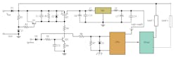
Under normal conditions, when the ignition switch is kept on, Q3 stays on and also maintains Q2 on. Q1 is usually off and turns on only when the bus voltage exceeds 33 V dc, governed by the 32-V zener, Z1 (under transient and other overvoltage situations).
When the ignition key is turned off, Q3 stays on for a time governed by R5, C2, and R6 to hold Q2 on. Since Q2 is directly connected to the battery through D1, the circuit remains powered as long as Q3 and, hence, Q2 is on.
However, the CPU senses the ignition off condition through one of its inputs and starts performing “cleanup” operations, such as storing the data logged in RAM to EEPROM during the breather provided to it by the R5-C2-R6 delay circuitry. This clever scheme obviates the need for the electromechanical relay that’s usually used, reducing cost and eliminating cumbersome wiring.
During an overvoltage/bus transient condition exceeding 33 V dc, Q1 turns on due to the 32-V dc zener in its base circuit. It switches off Q2, protecting the load-circuit from high voltages.
A tricky situation arises when a transient arrives while the CPU is logging its data in RAM under normal operation. Q2 will switch off and power to CPU will disappear, requiring a power-on reset when the transient goes away and Q2 restores the power. This is highly undesirable since it would interfere with the integrity of the data being written in RAM.
This problem can be addressed by putting the CPU to sleep during the transient period (usually a few hundred milliseconds) and waking it up when the transient goes away. Doing this avoids a hard reset under such situations.
Capacitor C8 keeps the CPU alive during the sleep mode. An extremely low CPU current avoids draining C8 during the transient period, avoiding a CPU power-reset. The CPU can also turn off output power drivers during the transients to protect them from high current spikes.
About the Author
Vishwas Vaidya
Vishwas Vaidya was assistant general manager of the electronics division at Tata Motors. He is based in Pune, India. He holds a master's degree in control engineering from the Indian Institute of Technology, New Dehli, India.
Comment About the Article
To join the conversation, and become an exclusive member of Electronic Design, create an account today!

Leaders relevant to this article: