Is the Thermal Resistance of LEDs Constant?
An LED's junction-to-ambient temperature thermal resistance is a measure of its ability to dissipate heat from its junction-to-ambient air, which is a function of its chip size and package.
In terms of thermal resistance (Rth), most power LEDs dissipate heat from the junction-to-the case (slug), from case-to-heat sink, from heat sink-to-enclosure, and enclosure-to-ambient air , that is:
R(th)j-a = R(th)c-h + (Rth) h-en + (Rth)en-a (1)
Where:
(Rth)j-a = Thermal resistance from junction-to-air
(Rth)j-c = Thermal resistance from junction-to-case
(Rth)c-h = Thermal resistance from case-to-heat sink
(Rth)h-e = Thermal resistance from heat sink-to-enclosure
(Rth)en-a = Thermal resistance from enclosure-to-air
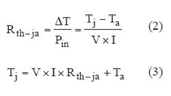
LED junction-to-ambient thermal resistance is:
Where:
ΔT = LED temperature difference after reaching equilibrium
Tj = LED junction temperature
Ta = LED ambient temperature
V = LED forward voltage drop
I = LED current in amperes
Pin = Power input in watts
Superficially, power LEDs and power transistors are very similar in the way heat is conducted from the semiconductor junction-to-ambient. However, LEDs have a parallel path for power to flow that transistors don't have. That is, the transistors do not exhibit power converted to light and radiated directly to the ambient air. Due to this radiation path and the difficulty in measuring LED junction-to-ambient temperature directly, many researchers doubt whether the thermal resistance of LEDs is indeed a constant [1] [2] [3] [5][6].
LED junction-to-ambient thermal resistance affects the electricity to light conversion efficiency, so life expectancy, as well as color shift, and the question of constant thermal resistance is important.
Many researchers use indirect methods to measure LED thermal resistance [2] [3] [7]. Measuring the heat sink or metal core PCB temperature, then adding the calculated junction-to-heat sink temperature, we can estimated the junction-to-ambient temperature [5] [7] and thereby estimate the junction temperature. Others prefer to use non-contact methods to evaluate the thermal resistance [3], but using such indirect methods leads to the conclusion that the thermal resistance changes with the drive current, input power, ambient temperature and luminous flux output [5] [2]. Here, we propose to use a direct measurement method [4] to find out whether junction-to-ambient thermal resistance is constant or not.
Instruments used include:
- Junction Temperature Tester by Acorn Technology is an EIA/JESD51-1 compliant instrument that measures LED junction temperature directly. This instrument uses dynamic mode cyclic testing method outlined on page 9 of the EIA/JESD51-1 standard.
- Temperature-controlled environmental chamber with 60W heater and Auber Instruments PID Controller.
- Digital light meter.
MEASURING LED JUNCTION-TO-AMBIENT TEMPERATURE
Measuring junction temperature with the Acorn Tester follows a three-step procedure. This tester uses an ambient reference LED and a 10-turn potentiometer setting to emulate the forward drop of a DUT (device under test), at ambient temperature and 100µA. The procedure can be explained with the following:
IM = 100µA for both the reference LED and the DUT
Vj = Forward drop of DUT at any junction temperature
Va = Forward drop of DUT at ambient junction temperature
G = Gain to convert (Vj -Va) to Tj-a (10mV/°C), which allows the meter to read °C directly.
The temperature coefficient of an LED is negative, so we multiply G by -1.
Step 1. Zero the test.
Vj and Va are forward drops of the same LED at different temperatures
At ambient temperature Vj = Va. Because of this, they don't exist at the same time. To find Vj -Va we have to create a voltage that equals Va at ambient, but stays constant when the junction temperature changes. To accomplish this, we use another LED as reference and a zero potentiometer to compensate the difference in forward drop between the two LEDs. When both LEDs are at ambient, adjust the zero potentiometer until Tj-a equals zero.
Vref + Vzero = Constant
Continue to next page.
Step 2. Calibrate the gain.
With the switch position at calibrate both DUT and reference LED have 100µA through them.
Place the DUT in a temperature-controlled box and raise temperature T j-a 40°C above ambient. Then, adjust the gain potentiometer until the center meter reads 40.0. The sensitivity of this instrument is now 10mV/°C. This step enables us to read LED junction temperature in degree C directly.
Now, you have finished calibration of the LED and can proceed to drive it and measure the thermal resistance.
Step 3. Run the test.
At this mode, the LED is toggled between drive current, ID (99 ms) and IM (1 ms). The temperature measurement is only taken during the 1 ms when I = IM. This enables us to heat the LED junction with ID and at the same time measure the junction temperature with IM.
The curve in Figure 1 is recorded with a transient recorder in real time. This curve actually is made of 1700 data points over 170 seconds. The first 20 seconds, the temperature increases at a rapid rate, then the temperature increases gradually and slows down until it reaches equilibrium.
RESISTANCE CONSTANT
An older HP 5 mm red AlInGaP LED was used for the first DUT (Table 1). It has a copper lead frame and it can be driven to 100 mA. Experiments clearly show that the thermal resistance doesn't change with drive current. When the drive current changed from 20 mA to 100 mA in five steps, the largest thermal resistance deviation from the mean is only -0.98%.
The second experiment was performed with a Cree 5 mm green LED (Table 2). Its thermal resistance is still constant. This and other experiments prove that with different color LEDs the thermal resistance is still constant.
The experiment in Table 3 was performed on an orange, AlInGaP power LED. It is mounted directly to a FR4 board so one can consider that it has no heat sink. The largest drive current used is 200 mA because the junction temperature already reached 91°C at 20°C ambient. At 200 mA drive current, the apparent thermal resistance increased by 1.91% because the forward voltage drop is lower than at lower drive currents. However, for all practical purposes the thermal resistance is constant. From 50 mA to 200 mA the output flux increased by 2.54 (910/358) times and the thermal resistance is still constant.
HEAT SINK CUTS THERMAL RESISTANCE
Another orange AlInGaP power LED is used in this experiment (Table 4). This LED is mounted on a aluminum heat sink mounted in a vertical position. This will make the thermal resistance much smaller than the LED tested in experiment 3. The heat sink helps the LED maintain even a more consistent thermal resistance.
In Table 5 we are still using the LED on heat sink from experiment 3, except cool air is blown at the heat sink to further reduce the thermal resistance, while the thermal resistance is still invariant.
To prove that the ambient temperature changes do not influence the thermal resistance, the experiment shown in Table 6 is repeated using a different orange LED, also mounted on a heat sink. The ambient temperature is measured with a thermocouple attached to the heat sink. When the ambient increases by 5°C, the ΔT also increased by 5°C. The data points show a slight increase of thermal resistance when the ambient temperature increases. This is because the forward voltage of the LED decreases when junction temperature increases. For all practical purposes the thermal resistance is still constant even when the ambient temperature changed 30°C.
REFERENCES
Electric and thermal transient effects in high power optical devices, by Gabor Farkas, Shatil Haque, Frank Wall, Paul S. Martin, Andras Poppe, Quint van Voorst Vader, Gorgy Bognar
Characterization of Thermal Resistance Coefficient of High-power LEDs by Jayasinghe, Gu, Narendran, Lighting Research Center, Rensselaer Polytechnic Institute
A Non-contact Method for Determining Junction Temperature of Phosphor-Converted White LEDs. Gu, Narendran, Lighting Research Center, Rensselaer Polytechnic Institute
USPN 7,052,180 LED Junction Temperature Tester, Kelvin Shih
Is the Thermal Resistance Coefficient of High-power LEDs Constant? Jayashinghe, Dong and Narendran
Thermal Investigation of High-power Optical Devices by Transient Testing, by Gabor Farkas, Quint van Voorst Vader, Andras Poppe, Gyorgy Bognar
Characterizing the Thermal Resistance Coefficient of LEDs, completed research, Lighting Research Center, Rensselaer Polytechnic Institute
Comment About the Article
To join the conversation, and become an exclusive member of Electronic Design, create an account today!

Leaders relevant to this article: