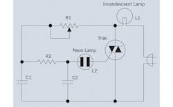
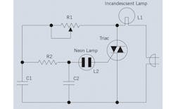
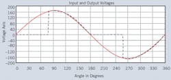
To understand the technology associated with practical LED dimming we first have to look at the technology associated with triac-based incandescent lamp dimmers. The typical triac lamp dimmer circuit consists of the relatively simple circuit shown in Fig.1. Because the triac acts like two back-to-back silicon controlled rectifiers it can conduct in either direction. Therefore, the triac dimmer circuit cuts both halves of the ac sine wave input, as shown in Fig. 2. Varying potentiometer (R1) varies the amount of the ac waveform that is cut, which varies the incandescent lamp brightness.
There are major differences between driving an incandescent and LED lamp, which are related to load impedance and response time to an applied voltage. The incandescent lamp is resistive so the voltage and current through the lamp have a linear relationship. Due to the thermal inertia of the incandescent lamp’s filament, the pulsed input voltage of Fig. 2 does not cause the light output to flicker. In contrast, the LED is a nonlinear load in which lamp current and voltage depend on the diode-like performance of an LED.
fig. 1
fig. 2
Furthermore, the LED responds much faster than an incandescent lamp to changes in applied voltage. Thus, the 120 Hz triac drive voltage can appear as flicker using an LED, unless a “smart” LED driver modifies the triac output to eliminate flicker. Flicker is an issue with LED lamps, as explained in the sidebar, “Look Out For Flicker.”
Among the new “smart” LED drivers intended for use with existing triac dimmers are iWatt’s iW3616 and iW3617. They are two-stage AC/DC power supply controllers optimized for dimmable LED luminaires. The iW3616 is rated at 12W and the iW3617 has a 25W rating. Both controllers are compliant with the IEC61000-3-2 standard for electromagnetic compatibility (EMC). Incorporating iWatt’s proprietary Flickerless™ technology, they automatically detect the dimmer type and phase, providing compatibility with analog and digital dimmers. Flickerless technology also removes virtually all visible and invisible LED flicker to provide a stable light output under all conditions.
A triac dimmer normally requires a high-power bleeder resistor across the load, which increases solution size and cost. The iW3616 and iW3617 do not require the bleeder resistor.
Both the iW3616 and iW3617 are compatible with solid-state lighting industry standard Zhaga for hot-plug LED modules and also incorporate mapping options for the dimming function that falls within the NEMA SSL6 dimming curves for incandescent replacement bulbs. They simplify dimmer design and provide a very robust solution by integrating iWatt’s EZ-EMI® technology.
Features include the ability to run off of an emergency backup DC voltage rail in the event of a power outage and a temperature protection circuit that reduces the output drive to the LEDs to protect against overheating while maintaining light output. They also incorporate iWatt’s proprietary PrimAccurate™ primary-side control technology, which minimizes external component count.
The iW3616 is available in two versions, the iW3616-00 optimized for 120 VAC input applications and the iW3616-01, optimized for 230VAC applications. The iW3617 is available in two versions, the iW3617-00 optimized for 120 VAC input applications and the iW3617-01, optimized for 230 VAC applications.
Operation
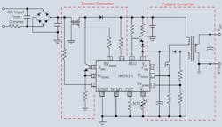
The power factor correction (PFC) and dimmer interfacing block control the boost converter as the first power stage in the iW3616 system (Fig. 3). It analyzes the rectified AC waveform and determines whether a dimmer is connected on the line. If no dimmer is connected, the block switches the boost BJT (BDRV pin) for PFC and stores the energy in the boost output capacitor. PFC operation depends on the input voltage (VIN pin), the boost output voltage (VCB pin), and the magnetic flux status of the boost inductor (BVSENSE pin). If a dimmer is connected, the block detects the type of dimmer by analyzing the shape of the rectified AC waveform (VIN pin). It then provides a dynamic impedance to interface the dimmer by driving the boost BJT (BDRV pin). The purpose is to match the load requirement of the dimmer while storing the energy in the boost output capacitor. To provide accurate impedance, the gain (β) of the boost BJT is calibrated by the BISENSE pin. This block also measures the dimmer phase conduction angle to determine the dimming level.
The LED current regulation and dimming control block control the flyback or buck/boost converter as the second power stage (Fig. 3).
fig. 3
It switches the flyback MOSFET (FDRV pin) to supply constant current to the LED load from the energy stored in the boost output capacitor. The constant current regulation algorithm is based on the information of the transformer primary-side peak current (FISENSE pin) and magnetic flux status of the flyback transformer (FVSENSE pin). This block also dims LEDs by adjusting the output current based on the dimmer phase conduction angle provided by power factor correction and the dimmer interface block.
Wall Dimmer Retrofit
There are two basic types of phase-cut wall dimmers: leading-edge dimmers and trailing-edge dimmers. If the AC voltage rises at the phase-cut edge, the dimmer is called a leading-edge dimmer. Otherwise it is called a trailing-edge dimmer. Normally speaking, the leading-edge dimmer is triac-based (R-type, RL-type); the trailing-edge dimmer is MOSFET or IGBT-based (RC-type).
With advanced dimmer detection technology, the iW3616 and iW3617 can operate with most wall dimmers. When no dimmer is on the line, the iW3616 and iW3617 optimize the power factor and minimize the current harmonic distortion on the AC power line.
Besides eliminating the bleeder resistor, the iW3616 and iW3617 minimize the external components count by simplifying the EMI filter, and not requiring an optocoupler. Also, there is no need for a secondary-side feedback circuit or any components for loop compensation.
Regulations around the world mandate the driver performance, as well as efficiency. Quality is specified in terms of total harmonic distortion (THD) and power factor and the iW3616 and iW3617 exceed all requirements, achieving power factor greater than 0.95 and low total harmonic distortion (THD) of less than 15%. Both devices are designed to meet, or exceed the 85% efficiency required for most new LED driver designs.
The iW3616 and iW3617 build on iWatt’s existing15W iW3614 LED driver by expanding dimmer compatibility, and improving dimming and EMI performance. This is achieved by replacing FETs with lower cost BJTs, by reducing the component count needed for the protection circuit and EMI filtering, and by using a smaller, lower-cost E-capacitor.
Both controllers operate with dimming frequencies from 630Hz to 900Hz and allow smooth, flicker-free dimming from 1% to 100% with tight ±5% LED current regulation. Comprehensive safety features include LED open/short circuit protection, input overvoltage protection, overtemperature thermal shutdown, and AC line over-voltage/frequency protection.
LED Lifetime
An important concern with LED-based bulbs is their lifetime. An LED is a semiconductor, so the higher the operating junction temperature, the lower the expected life. One way to ensure long operating life is to de-rate the current driving the LED and simply use more LEDs to produce a specific light output. A lower junction temperature will reduce LED heating and extend life at the cost of more LEDs. However, it does not account for external factors, such as the physical properties of the light fixture, which may contribute to higher than expected heating.
Another method is to establish a desired maximum junction temperature at which the LED current needs to be reduced to prevent degradation. Fig. 3 shows an NTC (negative temperature coefficient) resistor connected to the VT pin that acts as a temperature monitor when placed physically near the LED cluster. Then, if the LED cluster reaches the maximum programmed temperature threshold, the controller reduces the LED current by 10% increments until the temperature stabilizes. If the temperature drops, the LED current steps back up to its maximum programmed value in equal and opposite 10% increments, with an appropriate amount of hysteresis to prevent oscillations. A fail-safe mode exists where the current through the LEDs reduces to 1% of programmed output current, in the event of a major failure event.
Related Articles:
Buck LED driver with Active PFC
LED Power Management: Techniques Proliferate
Next-Generation Solid-State Lighting Fixtures Need Optimized LED Drivers
About the Author

Sam Davis
Sam Davis was the editor-in-chief of Power Electronics Technology magazine and website that is now part of Electronic Design. He has 18 years experience in electronic engineering design and management, six years in public relations and 25 years as a trade press editor. He holds a BSEE from Case-Western Reserve University, and did graduate work at the same school and UCLA. Sam was the editor for PCIM, the predecessor to Power Electronics Technology, from 1984 to 2004. His engineering experience includes circuit and system design for Litton Systems, Bunker-Ramo, Rocketdyne, and Clevite Corporation.. Design tasks included analog circuits, display systems, power supplies, underwater ordnance systems, and test systems. He also served as a program manager for a Litton Systems Navy program.
Sam is the author of Computer Data Displays, a book published by Prentice-Hall in the U.S. and Japan in 1969. He is also a recipient of the Jesse Neal Award for trade press editorial excellence, and has one patent for naval ship construction that simplifies electronic system integration.
You can also check out his Power Electronics blog.


