Voltage Regulator Offers Overload Indication, Short-Circuit Protection
This voltage regulator delivers smooth control of a constant voltage from 0 to 8 V. It protects the load against short circuits and indicates connection, overload, and output level.
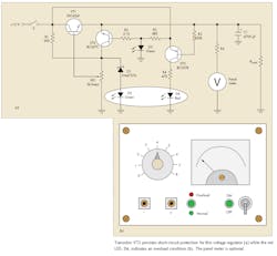
The series chain of Zener diode D1 (a 1N4737A) and green LED D2 (part of the two-color LED D2/D4) forms the voltage stabilizing element (see the figure). Potentiometer VR1 controls the output voltage level. LED D3 is an “on” indicator. Transistor VT2 provides short-circuit protection to the load, with red LED D4 indicting an overload. (D2 blows out simultaneously with an overload.) Short-circuit current does not exceed 38 mA. The regulator’s output current may reach 2 to 3 A if a heatsink is used with transistor VT1.
Separate green and red LEDs can be used for D2 and D4 if a two-color LED is not available. The panel meter indicates the output voltage level, but it is actually optional. R6 is a damping resistor whose value is determined experimentally and depends on the value of the panel meter’s internal resistance.
Anoop’s Analysis
Using a standard Zener regulator with a transistor as a current amplifier is neither new nor novel. However, the addition of overcurrent/short protection as well as overcurrent/short indication makes the circuit more useful than a typical Zener/transistor regulator. Yet designers should be aware of several factors before using it.
First, LEDs have widely varying forward voltage drops even within the green spectrum. Green LEDs vary from 1.7 V to 3.5 V. A Zener (D1) and an LED (D2) together serve as the voltage reference, so the forward voltage of the LED affects the output voltage range. Forward voltage of an LED is also sensitive to operating temperature and forward current.
Second, the author says short-circuit current is limited to 38 mA. But since there is no current sensing, it’s difficult to estimate the short-circuit current, so the current limit has to be determined indirectly.
When the output voltage drops due to over-current (or short) to below VD3 + VBE2 (typically 2.9 V), VT2 conducts and reduces the base current of pass transistor VT1, limiting the output current. Without knowing the load resistance, RLoad, one can not estimate the maximum current in case of an overload or short-circuit.
Third, since the current limit is applied at around 2.9 V, the circuit can not provide any output voltage less than 2.9 V. The front-panel dial indicates that output voltage can be between 0 V and 8 V, which is not attainable.
Fourth, because of the issue of varying LED forward voltages, each regulator built will have to be calibrated separately. Since there is no calibration capability in this circuit, the voltage setting dial may have to be marked differently for each regulator that uses different batches of green LEDs.
Fifth, adjustable resistor VR1 (5 kΩ) determines the output voltage. But since the base current of power transistor VT1 flows through VR1, and the base current depends on the output voltage, the output voltage and maximum output current are linked. The higher the output voltage, the lower the output current capacity will be.
Finally, to eliminate the effect of VT1’s base current on the voltage at VR1’s slider, replace VT1 with an n-channel MOSFET.

