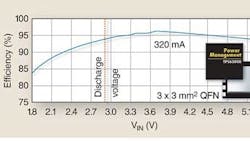
Texas Instruments’ TPS63000 helps extend battery life in smart phones, digital still cameras and other single-cell, Li-ion-powered devices by providing high-efficiency buck-boost power conversion. The monolithic dc-dc converter delivers up to 96% efficiency while operating from a 1.8-V to 5.5-V input (Fig. 1). While operating in the stepdown mode, the chip will deliver up to 1200 mA at 3.3 V from a 3.6-V to 5.5-V input. In the stepup mode, the IC will produce up to 800 mA at 3.3 V from a 2.4-V or greater input. The chip automatically switches between stepdown and stepup modes.
In single-cell Li-ion applications, the battery voltage varies from a charge voltage of 4.2 V down to a discharge voltage of about 3 V. To generate a 3.3-V supply, the battery voltage may be stepped down efficiently using a buck converter. In fact, a buck converter such as TI’s TPS62046 will step down the battery voltage more efficiently than the new TPS63000.
However, the buck-boost converter continues to operate after the battery voltage drops to 3.3 V. As a result, the TPS63000 buck-boost converter can provide up to 28% greater run-time compared to a high-efficiency buck converter in the same 3.3-V application. The TPS63000’s ability to operate over a wide input voltage range will become even more of an advantage as new Li-ion cells emerge with higher charge voltages and lower discharge voltages.
According to the vendor, the TPS63000 also provides greater efficiency than existing buck-boost converters. The chip’s high performance is achieved using a unique topology, which essentially takes a dual-stage approach and combines a buck converter and a boost converter on one chip.
This approach uses a single inductor, but includes the power switches for both the boost and buck circuits (Fig. 2). The resulting circuit resembles an H-bridge buck-boost converter, but is driven differently to optimize efficiency and reduce stress on the passive components.
In the TPS63000, the control circuit ensures that only one of the converter circuits is on at a time, while keeping the other converter in a passive state. For example, when the boost converter is required, the buck converter is operating in a 100% duty-cycle mode. And when the buck converter is needed, the boost converter is operating in 0% duty-cycle mode. Implementing this form of buck-boost operation adds complexity to the control circuit, but results in the high efficiency shown in Fig. 1.
The TPS63000 operates at a fixed switching frequency and employs synchronous rectification. Quiescent current is less than 30 µA, and the chip enters a power-save mode at low-power operation. This mode can be disabled. In addition, the converter itself can be disabled to minimize battery drain. During shutdown, the load is completely disconnected from the battery.
The TPS63000 comes in a 3-mm x 3-mm, 10-pin QFN PowerPAD package. In the future, the company plans to introduce buck-boost converters in the even-smaller chip scale packages. Available now in volume production, the TPS63000 is priced at $2.75 in quantities of 1000. Evaluation modules of the TPS63000 and application notes are available at www.ti.com/tps63000-pr.
