Hybrid powertrains get isolated for safety
Consider today's Prius. It has a main battery voltage of about 200V. It carries dc/dc converters to step down the main battery voltage to 12 V for charging the auxiliary battery and to power auxiliary circuits. The car also needs additional step-downs for 5-V, 15-V and 24-V supplies that power various kinds of circuits in the car.
The converters that handle the necessary voltage reduction in the Prius must incorporate galvanic isolation as a safety measure. The situation is no different in EVs and plug-in HEVs where both on-board and off-board chargers use ac/dc converters to take power from the power grid. These chargers are typically high-power converters ranging from a few hundred watts up to 2 kW, with output voltages between 48 and 300 V.
Galvanic isolation between primary and secondary circuits is necessary for both ac/dc and dc/dc converters because of the hazardous high voltages. Standards and regulations for HEVs are still being worked out, but a handful of international/national standards already apply.
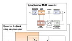
Makers of optocouplers, such as Avago Technologies, are now turning their attention to the isolation requirements of such supplies. The firm's R2Coupler series is designed to meet the insulation requirements for these emerging automotive applications. In isolated ac/dc and dc/dc converters, optocouplers often are the technology of choice for error amplifier feedback. According to Avago, optocouplers often work out better than alternatives such as transformers because they can cost less and are smaller. And when transmitting dc signals, use of transformers can also necessitate complex signal conditioning circuits.
The optocouplers used in HEV applications must have a relatively quick response because the power supplies in these vehicles use a high pulse width modulation (PWM) frequency to keep down the size and weight of the power transformer — 200 kHz is typical, with a cut-off frequency between 10kHz and 50kHz. The four-pin phototransistor found in many consumer power supplies generally can't handle such frequencies. That's because it has a relatively large photodiode capacitance between base and collector, multiplied by large voltage gain. As a result, the typical bandwidth of a phototransistor is on the order of 10 kHz. There is a significant phase delay introduced at the frequency of interest and designers must build in compensation to give these devices a sufficiently large bandwidth and dynamic performance to handle higher frequencies.
Avago Technologies, http://avagotech.com
