High-Voltage Synchronous Regulators Address Industrial Power Dilemma
Industrial-automation system design presents unique challenges. This is, in fact, the story of conflicting demands. The introduction of low-cost modular racks to house system components such as programmable logic controllers (PLCs) and I/O modules places severe space and thermal restraints on the engineer and the solution. Such challenges are compounded by the need to ensure highly reliable operation in harsh environments subject to dirt, humidity, and vibration.
Related Articles
- Next-Gen MOSFETs Up Efficiency of Synchronous Buck Converters
- Back to Basics: Voltage Regulators Part 2
- The eGaN FETShootout Volume 7: Buck Converters
- Improving Efficiency in Synchronous Buck Converters
- Fully Integrated DC-DC Converters
- Power Management 101: Converter & Controller ICs
Customers, moreover, expect enhanced functionality in subsequent generations of automation systems, and all without an associated increase in power consumption, equipment size, heat generation, and cost. That enhanced functionality is typically underpinned by advances in electronics technology, but often comes at a cost: tighter power tolerances and proliferation of voltage levels that must be kept stable while being derived from a less-than-perfect mains supply.
And yet, the engineer does not want to spend valuable project time designing a power supply that goes unnoticed by the customer and is often considered as wasting valuable real estate. Instead, the engineer prefers to focus on the things that clearly differentiate his automation system from the competition.
Semiconductor vendors have responded to the industrial-automation system designer’s conflicting demands by introducing modules that integrate many of the key functions of a power supply in a single device. However, modules designed to operate from the 12, 24, or 48 VDC supply used by industrial automation systems must either be protected by voltage clamps or use asynchronous switching technology to withstand the voltage spikes that plague the mains power source. Both solutions result in larger, more expensive and less efficient power systems—precisely what the system engineer is trying to avoid.
But now there is a new generation of power devices that take advantage of the latest silicon manufacturing techniques allied to innovative chip design. New power supplies incorporate synchronous switching technology, yet can withstand voltage spikes up to 60 V and supply up to 2.5 A, something that was previously impractical. These capabilities ease industrial automation system power-supply design by improving efficiency and, in turn, lowering heat generation and power consumption, reducing component footprint, and limiting the number of discrete external components.
Industrial Control Architecture
While 24 VDC has become the de facto voltage for the majority of industrial-control applications (particularly those that employ PLCs), 12 VDC is also common, typically as a battery-backup voltage or supplied by an alternative energy source such as photovoltaic (PV) panels. The recent introduction of Power-over-Ethernet (PoE) has also encouraged manufacturers of industrial automation to design equipment that operates from the 48 VDC supply mandated by that standard.
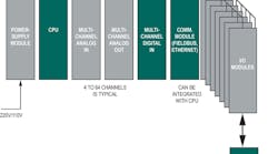
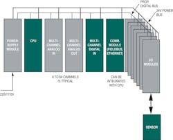
A typical industrial-control system employing a 24 VDC supply is shown in Fig. 1.
The system comprises I/O modules for receiving information from sensors or sending instructions to actuators, multichannel digital inputs, multichannel analog inputs and outputs, communications functions, and a processor (CPU) linked by a digital bus. A PLC typically provides the computing muscle. Electrical power is supplied from the mains, stepped down to 24 VDC, and distributed via a backplane.
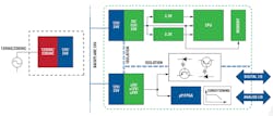
A closer look at the system’s power supply reveals greater complexity dictated by the different voltage and current levels demanded by the various system elements. Fig. 2 illustrates a small part of the power architecture. The 120 VAC/230 VAC mains supply is initially stepped down to the standard 12 VDC or 24 VDC system backplane supply using an industrial power module. At the system level this backplane voltage is then further stepped down to the lower voltage levels demanded by the individual components.
The PLC, for example, could comprise a microprocessor, digital signal processor (DSP), and field-programmable gate array (FPGA). These devices require voltages ranging from 5 V down to 1 V. Yet the PLC as a whole may require up to 3.5 A of current. Similarly, a multichannel analog I/O module requires both ±15 V and 5 V supplies for its various amplifiers, analog-to-digital converters (ADCs), and multiplexers (MUXes) with current up to 500 mA.
To make things just a little more complicated, the designer needs to take into account transient voltage spikes (“overvoltages”) that affect the mains supply through events such as lighting strikes on the distribution network, or by rapid switching of heavy loads that share the same mains circuit as the industrial automation system. Voltage spikes can also occur within the power-supply architecture itself, for example, when the power module steps down the mains voltage to 12 VDC or 24 VDC, particularly if a switch-mode type device is used.
These overvoltage occurrences are so common that organizations such as International Electrochemical Commission (IEC) advise engineers to design their systems to withstand them. For example, IEC 60664, which deals with insulation coordination in low-voltage (1 kVAC and 1.5 kVDC) systems, notes that “Category-II” equipment (which includes the type of equipment used for industrial automation) powered from a mains-derived 24 VDC supply should be designed to withstand overvoltages up to 60 V.
Fundamentals of DC-DC Voltage Regulation
DC-DC voltage conversion (or “regulation”) is big business and semiconductor vendors have invested large sums to develop a wide range of products for all applications. Devices break down into two groups, low-dropout voltage regulators (LDOs), also known as linear regulators, and switching voltage regulators.
When carefully matched to the operational characteristics of the application, switching regulators are generally more efficient across a wide input-voltage range compared to LDOs. Moreover, switching regulators can step up (“boost”), step down (“buck”), and invert voltages with ease. (Note that voltage inversion is required for some parts of an industrial-automation system’s power supply.) In contrast, LDOs can only buck voltages.
There is one drawback of switching regulators compared to simple-to-use LDOs: the regulators have a more complicated design. This happens because output filtering is needed to attenuate voltage and current ripples generated by the high-frequency switching operation. This will present problems for sensitive chips and it generates electromagnetic interference (EMI). Nonetheless, engineers designing many contemporary applications increasingly favor switching regulators.
The key to the operation of a switching regulator is the use of a metal-oxide semiconductor field-effect transistor (MOSFET) as the switching device. When the MOSFET is on, current flows both to the load and an external inductor that stores the energy. When the MOSFET switches off, the inductor supplies its stored energy to the load.
Pulse-width modulation (PWM) is generally used to control the output voltage. The frequency is held constant and the pulse width (“on-time”) is adjusted to deliver the required voltage. The high-frequency switching of the voltage regulator limits losses in the system while maintaining a relatively steady voltage output over a range of inputs and loads.
In an "asynchronous" topology switching regulator (see Fig. 3), the energy stored in the inductor and then delivered to the load during the MOSFET’s off cycle does not flow directly to the load, instead travels via an external Schottky diode. Provided that the inductor is selected according to the anticipated load, the switching regulator will operate in a continuous conduction mode, thus supplying a steady, regulated voltage.
The ultimate efficiency of this type of switching regulator, known as the “asynchronous” type, is primarily determined by two factors: the external Schottky diode’s forward voltage drop, and the device’s reverse-leakage current characteristics. The forward voltage drop has approached a limit of around 0.3 V in modern devices. That does not sound like much, but it does cause a constant drain on the device and reduces efficiency.
Replacing the Schottky diode with a MOSFET improves efficiency because the on-resistance (RON) of the transistor can be lowered using advanced manufacturing techniques that make its forward voltage (and hence losses) lower than the original diode. The operation of the two MOSFETs in this circuit must be synchronized such that one is on while the other is off (see Fig. 4).
The second MOSFET of a so-called synchronous regulator can be integrated into the module. In addition to eliminating the external Schottky diode, this eases circuit design and reduces the Bill-of-Materials (BOM).
One side effect of the synchronous regulator’s design is that current flows in both directions in the inductor due to the switching operation of the two MOSFETs (i.e., doubling the inductor’s losses). This is compared to the single direction of flow in the asynchronous type. The losses are typically small in a synchronous regulator, but can become more significant at lower loads where the device’s efficiency could be lower than an equivalent asynchronous type.
Major semiconductor vendors have addressed this drawback using a number of technologies. Maxim Integrated, for example, has introduced a range of high-voltage synchronous voltage regulators like the MAX17503 that have three selectable modes of operation: PWM, pulse-frequency modulation (PFM), and discontinuous-conduction mode (DCM). PWM is used for normal operation. PFM improves efficiency at lower loads by eliminating reverse inductor current and skipping pulses. DCM also eliminates reverse inductor current for better efficiency at lower loads, but does not skip pulses. This makes DCM suitable for frequency-sensitive applications.
A New Breed of Synchronous Regulators
Synchronous voltage regulators would seem to be the perfect answer to meet the challenges of industrial-automation system power-supply design. The devices are efficient, limit power consumption, and lower system temperature. They require little space and reduce BOM costs.
There are many synchronous regulators rated for up to 28 V operation and a few up to 40 V. However, the majority of these devices are particularly sensitive to overvoltage, because there is little margin between their operating and absolute maximum voltage ratings. The voltage spikes endemic to mains-powered systems would likely destroy these components quickly.
One solution is to protect the synchronous regulator with a protective clamp that limits the voltage spikes to a level below the component’s absolute maximum rated voltage. However, these clamps add cost, take up space, and extend the design schedule, thereby negating many of the benefits for using a synchronous regulator in the first place. This presents the industrial automation system engineer with a dilemma: does s/he benefit from the higher efficiency of a synchronous regulator and accept the additional hassle of voltage clamping, or does s/he choose an asynchronous regulator that can handle the likely system overvoltages yet consumes more power and gets hotter?
Semiconductors vendors have invested heavily in R&D to resolve this dilemma and a few devices that can handle input voltages up to 60 V or even 75 V are now entering the market. However, these devices are limited to just a few hundred milliamps output current, which is far short of the requirements of much of the equipment used in industrial automation systems, particularly PLCs.
But now, a new generation of high-voltage, high-output-current synchronous regulator has hit the market. An example of these new high-capability chips is the MAX1750x family from Maxim Integrated. The devices integrate two MOSFETs and eliminate the external Schottky diode plus its associated external components.
This new synchronous regulator module family can handle up to 60 V and offers current outputs including 500 mA and 1 A. The company can also supply related products with outputs down to a few tens of milliamps for industrial automation system sensors using a 4–20 mA loop.
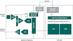
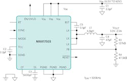
The MAX17503, for example, is designed to deliver up to 90% efficiency and runs up to 50% cooler than competing high-voltage asynchronous regulators. The device operates over a 4.5 V to 60 V input voltage range and delivers up to 2.5 A output current. Fig. 5 shows where the MAX17503 (and sister product MAX17501) is typically employed in an industrial-automation system.
Further, the MAX17503 saves up to 50% board space and reduces component count by up to 75%. High-frequency switching from 200 kHz to 2.2 MHz allows the external inductor to shrink to save more space.
In addition, the MAX1750x incorporates a PFM feature. PFM works by disabling reverse inductor current and skipping pulses at light loads. The advantage of PFM is higher efficiency at light loads because of lower quiescent current (IQ) drawn from the supply.
The high level of integration exhibited by the MAX1750x not only reduces the number of external components and decreases cost, but it also eases the design challenge. There is no need for the engineer to calculate the values for—and source—external capacitors and compensation resistors because the job has already been done for them. Fig. 6 shows an application circuit for the chip.
High-voltage, high-output synchronous voltage regulators meet the industrial-automation system designers' demanding requirements for compact, efficient, and easy-to-design-in power modules. Although the current selection of suitable components is limited, the range is sure to expand in the near future to cover all the dc/dc voltage conversion requirements of a typical system across power outputs from a few hundred milliamps up to several amps.
By resolving the industrial automation system power dilemma, a new generation of synchronous regulators has freed engineers to focus on optimizing the operation of their industrial automation systems, rather than struggling to come up with a robust power supply.
About the author:
Viral Vaidya is a Senior Business Manager for industrial power products at Maxim Inc. He has close to eight years experience in product management for various power management products. He has been at Maxim three years and served in a similar role the previous five years. Vaidya has a MSEE from San Jose State University in California.
