3 A Step-Down, Switch-Mode Regulator Squeezes Into Ultra-Thin LGA Package
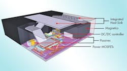
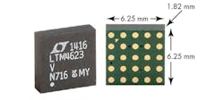
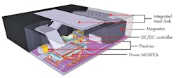
IC package size has become a key design consideration as electronic systems shrink. This is apparent in Linear Technology’s LTM®4623, a complete 3 A step-down, switch-mode regulator in an ultra-thin 6.25 mm × 6.25 mm × 1.82 mm LGA package (Fig. 1). Included in the package are the switching controller, power FETs, inductor and support components, as shown in Fig. 2. This micromodule regulator requires only four external components: input capacitor, output capacitor, resistor to set VOUT, and a capacitor for VOUT tracking and soft-start.
Related Articles
- Step-down Switching Regulator Powers 5-V USB Apps
- Step-Down Regulator Delivers Dual 1 A Outputs
- Synchronous Step-Down Regulator Is Good To +150 °C
- Step-Down Regulator Delivers 70 W In 4.5 cm² Package
- Synchronous Step-Down Regulators With DDR Memory
- Step-Down DC/DC Converter Delivers 96% Efficiency
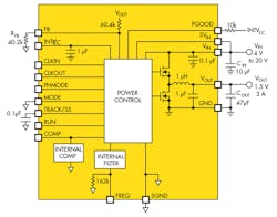
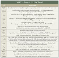
Despite its small size the LTM4623 duplicates many features of its larger cousins. As shown in Fig. 3, it is a standalone non-isolated dc-dc power supply. It provides precisely regulated output voltage adjustable between 0.6 V to 5.5 V via one external resistor when operating from a 4 V to 20 V input voltage range. With an external bias supply above 4 V , this module can operate from a 2.375 V input. Protection features include overvoltage, overcurrent and overtemperature. Table 1 describes the pin functions of the LTM4623.
You can use one external resistor to set the LTM4623’s switching frequency from 800 kHz to 4 MHz. The default operating frequency is 1 MHz without an external resistor. An external 162k resistor sets the operating frequency to 2 MHz, which optimizes inductor current ripple. You can synchronize the frequency to a clock within ±30% of the set frequency.
Current Mode Control
With current mode control and internal feedback loop compensation, the LTM4623 has sufficient stability margins and good transient performance using a wide range of ceramic output capacitors. Current mode control provides cycle-by-cycle fast current limiting. Foldback current limiting is provided for an overcurrent condition caused by a drop in VFB that reduces inductor valley current to approximately 40% of its original value. Internal output overvoltage (OV) and undervoltage (UV) comparators pull its open-drain PGOOD output low if the output feedback voltage changes a ±10% window around its regulation point.
For output loads greater than 3 A, you can parallel multiple LTM4623s to provide more output current without increasing input and output voltage ripple. For paralleling, connect the CLKOUT signal to the CLKIN pin of the following LTM4623 stage to line up both the frequency and the phase of the entire system. This provides a 2-phase, 3-phase or 4-phase operation. You can cascade a total of 12 phases to run simultaneously out of phase with respect to each other.
A multiphase power supply significantly reduces the amount of ripple current in both the input and output capacitors. The RMS input ripple current is reduced by, and the effective ripple frequency is multiplied by, the number of phases used (assuming that the input voltage is greater than the number of phases used times the output voltage).
Setting Output Voltage
The regulator’s PWM controller has an internal 0.6 V reference voltage. As shown in Fig. 3, a 60.4k internal feedback resistor connects the VOUT and FB pins together. Adding a resistor, RFB, from FB pin to SGND programs the output voltage, according to:
You should connect the LTM4623 to a low AC impedance DC source. It requires a 10μF input ceramic capacitor for RMS ripple current decoupling. Bulk input capacitance is only needed when the input source impedance is compromised by long inductive leads, traces or not enough source capacitance. The bulk capacitor can be an aluminum electrolytic or polymer capacitor.
With an optimized high frequency, high bandwidth design, the regulator requires only a single low ESR output ceramic capacitor to achieve low output ripple voltage and very good transient response. You may need additional output filtering to reduce output ripple or dynamic transient spikes.
The regulator has a phase-locked loop consisting of an internal voltage controlled oscillator and phase detector. This allows the internal top output MOSFET turn-on to be locked to the rising edge of the external clock. A pulse detection circuit will detect a clock on the CLKIN pin and turn on the phase-locked loop. The pulse width of the clock has to be at least 100 ns. The clock high level must be above 2 V and clock low level below 0.3 V. During the start-up of the regulator, the phase-locked loop function is disabled.
Stability Compensation
The LTM4623’s internal compensation loop is optimized for use with low ESR ceramic output capacitors. In case more phase margin is required for the application, you can add an additional 100 pF feedforward capacitor (CFF) between the VOUT and FB pins. Linear Technology’s LTpowerCAD design tool is available for control loop optimization.
To protect the internal output power MOSFETs against transient voltage spikes, the LTM4623 constantly monitors the VIN pin for an overvoltage condition. If VIN rises above 23.5 V, the regulator suspends operation by shutting off both power MOSFETs. Once VIN drops below 21.5 V, the regulator immediately resumes normal operation.
Internal overtemperature protection monitors the regulator’s junction temperature. It turns off both power switches if the regulator’s junction temperature reaches approximately 160 °C, and turns them on again when the temperature drops to about 145°C.
LTM4623 modules do not provide galvanic isolation from VIN to VOUT. There is no internal fuse, but you can add a slow blow fuse with a rating twice the maximum input current to protect the regulator from catastrophic failure.
About the Author

Sam Davis
Sam Davis was the editor-in-chief of Power Electronics Technology magazine and website that is now part of Electronic Design. He has 18 years experience in electronic engineering design and management, six years in public relations and 25 years as a trade press editor. He holds a BSEE from Case-Western Reserve University, and did graduate work at the same school and UCLA. Sam was the editor for PCIM, the predecessor to Power Electronics Technology, from 1984 to 2004. His engineering experience includes circuit and system design for Litton Systems, Bunker-Ramo, Rocketdyne, and Clevite Corporation.. Design tasks included analog circuits, display systems, power supplies, underwater ordnance systems, and test systems. He also served as a program manager for a Litton Systems Navy program.
Sam is the author of Computer Data Displays, a book published by Prentice-Hall in the U.S. and Japan in 1969. He is also a recipient of the Jesse Neal Award for trade press editorial excellence, and has one patent for naval ship construction that simplifies electronic system integration.
You can also check out his Power Electronics blog.
