Members can download this article in PDF format.
The Universal Serial Bus (USB) increasingly finds use in industrial applications, where it can support software upload and configuration, assist with diagnostics and maintenance, and connect peripheral devices. However, USB was defined as a consumer-electronics interface, and it doesn’t inherently tolerate the noise disturbances, ground bounce, and ground potential differences found in industrial environments.
To overcome such limitations and meet the needs of a broad spectrum of factory-automation, medical-equipment, and power-delivery applications, you can implement a galvanically isolated USB interface. However, you will need to ensure that your interface complies with EMI standards and minimizes inter-symbol interference (ISI).
Sponsored Resources:
- Protect Designs with Low-Emissions USB 2.0 Compliant 480 Mbps Isolators
- Compensate for Channel Loss with Equalizer Settings on High-Speed USB Isolators
- Isolated USB Repeater
Galvanic Isolation
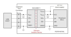
Texas Instruments offers a variety of isolated USB solutions that integrate a galvanic isolation barrier into a USB interface (Fig. 1). The company’s ISOUSB211 and ISOUSB111 isolated USB repeaters each provide high-voltage protection and enhanced signal integrity for USB 2.0 interface systems.
Both devices support charging-downstream-port (CDP) advertising, role-reversal, and automatic speed detection, which allows the same part-number device to be used for host, peripheral, hub, or cable isolation. In addition, both come in reinforced and basic isolation options, offering isolation voltages of 5,700 VRMS and 300 VRMS, respectively, in accordance with UL 1577.
Available in an SSOP-28 package, the ISOUSB211 supports the 480-Mb/s High Speed (HS) mode in addition to the 12-Mb/s Full Speed (FS) and 1.5-Mb/s Low Speed (LS) modes. The ISOUSB211 meets HS signal-quality requirements without the need for an external crystal oscillator or clock input. Its incremental jitter is low enough to meet USB eye-diagram specifications without retiming.
For applications not requiring high bandwidths, the ISOUSB111 supports LS and FS modes. It’s available in a 16-SSOP package that’s 40% smaller in size than a competitive device. The USB repeater also is available in a 16-SOIC package that’s pin-compatible with the competitive device.
EMC Performance
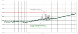
Electromagnetic-compatibility (EMC) performance is a key consideration when choosing a USB isolator for industrial applications. Figure 2 shows the emissions performance of the ISOUSB111 compared with that of a competitive device when used in a test setup with a 1-m cable between a PC and a USB drive. At one point, the ISOUSB111 offers emissions more than 20 dB lower than that of a competitive device, which fails to achieve compliance with the CISPR 32 Class B standard.
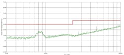
Figure 3 reveals the performance of the ISOUSB211 in a similar test setup. The ISOUSB211 meets the CISPR 32 Class B limit with significant margin. The noise peaking around 80 MHz is coming from an isolated power converter included on the ISOUSB211EVM evaluation module and not from ISOUSB211 itself.
Pre-emphasis and Equalization
A USB isolated repeater generates a fresh copy of its input signal across its isolation barrier, and input-signal jitter will appear at the repeater’s output. The repeater itself includes on-off keying circuitry that can contribute additional jitter. Total jitter on the repeater’s output is the root-sum-squared value of the input jitter and the jitter generated by the isolation circuitry.
You can minimize the adverse effects by choosing a repeater that includes transmitter pre-emphasis and receiver equalizer capabilities. These play a key role in improving signal integrity and reducing the frequency-dependent ISI caused by PCB trace losses.
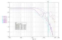
To investigate ISI, you can use an FR4 test printed circuit board having five differential-pair traces ranging from 6 in. to 4 ft. in length, and with each differential pair having USB connectors at each end. Figure 4 shows the measured differential insertion loss for each pair of traces. Longer traces have higher dc losses, and for all of the lengths, the insertion loss increases proportionally with frequency.
Figure 4 also illustrates ringing, which results from reflections due to impedance discontinuities along the traces. The insertion loss at high frequencies and the reflections increase ISI, which occurs when signals deviate from their ideal square-wave format. Transitions expand into adjacent intervals and signal levels never fully reach the ideal high- and low-voltage levels.
To mitigate these effects, the ISOUSB211’s transmitter offers nine programmable pre-emphasis settings, and its receiver offers nine programmable equalizer settings implemented with a continuous-time linear equalizer (CTLE) architecture.
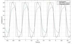
To a first-order approximation, the pre-emphasis/equalizer function provides compensation by amplifying high-frequency signals, peaking at 240 MHz, while keeping low frequencies unchanged. The result is reduced rise and fall times, allowing the compensated signal to get nearer to the ideal. Figure 5 shows uncompensated, compensated, and ideal waveforms.
In general, you can choose to use either pre-emphasis or equalization, depending on your setup. For example, if you’re using the FR4 test board with 6-in. to 4-ft. traces to make measurements, opt for transmitter pre-emphasis if you’re locating the test board between the USB repeater and the measurement instrument. On the other hand, use receiver equalization if you’re locating the repeater between the test board and the instrument. Figure 6 shows each configuration with the repeater mounted on an ISOUSB211DPEVM evaluation module.
However, if you’re using the repeater in a system that has differential trace loss greater than 2 dB, you should try to distribute the loss on both the upstream and downstream sides of the repeater. Then, use both receiver equalization and transmitter pre-emphasis simultaneously to compensate for the system loss.
Conclusion
USB isolators such as Texas Instruments’ ISOUSB211 and ISOUSB111 can adapt the consumer-centric USB interface for industrial applications. The TI devices easily meet EMI standards requirements, and the HS versions offer pre-emphasis and equalization settings to compensate for PCB-trace and other system losses.
Sponsored Resources:

