Members can download this article in PDF format.
Cameras are proliferating in automotive, industrial, agricultural, and other applications. In cars alone, they handle tasks ranging from lane-departure warning to parking assistance. But more cameras mean more lenses and more possibilities that lens contaminants will obstruct the cameras’ views. A new technology called ultrasonic lens cleaning (ULC) can remove those contaminants—it uses precisely controlled ultrasonic vibrations to propel ice, rain, and dirt away from a lens or transparent lens cover.
ULC is just one of several methods that can remove debris from lenses. Miniature windshield wipers, for example, or carefully aimed jets of liquid or compressed air also can remove contamination. Or you could set the lens to spinning, allowing centrifugal force to hurl debris away. These methods, however, are complex and expensive, and they present reliability issues. Unlike cleaning systems that rely on compressed air or fluids, a ULC system requires nothing more than a power supply and optional data line.
Natural Frequencies
ULC takes advantage of an object’s natural frequencies, which depend on its molecular structure and geometry. If you mechanically excite a glass, silicon, or polycarbonate lens or lens cover at one of its natural frequencies, it will resonate, with constructive interference creating a standing-wave pattern, or mode. A properly designed ULC will generate a standing wave of sufficient amplitude to blast ice, rain, dirt, insects, and other contaminants from a lens or lens-cover surface.
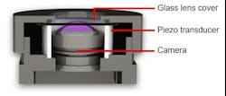
Piezoelectric transducers, which have proven their reliability through years of use in automotive and military/aerospace applications, are good fit for causing a lens or lens cover to vibrate in a ULC system. Figure 1 shows a cross section of the structure of a typical ULC system, with a piezoelectric ring transducer providing the ultrasonic excitation.
Although simple in concept, an effective ULC system must address several subtleties related to the design of the excitation circuitry and the configuration of the actuators. Piezoelectric transducers work by changing shape in response to a changing applied voltage. Thus, applying a fixed ac voltage at a natural frequency of the lens cover in Figure 1 should establish a single mode of vibration. A resonant frequency for a circular glass lens or cover that’s 10 to 40 mm in diameter and 0.5 to 2 mm thick will typically lie in the 20- to 100-kHz range.
However, as a lens or cover becomes contaminated, its natural frequency will change slightly. Consequently, a ULC system will typically sweep its frequency several kilohertz on either side of the target frequency—for example, it might sweep from 28 to 32 kHz for a target 30-kHz frequency to provide optimum cleaning.
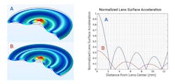
Even with this frequency sweeping, single-mode cleaning, represented by the simulation image at the top left of Figure 2, does have drawbacks. It imposes an acceleration gradient across the lens or cover, and lower acceleration points may clean poorly. Note the blue curve labeled A in Figure 2. You can see that it has nodes at distances of 2.5 mm, 5.5 mm, and so on from the center of the lens surface, where acceleration drops to zero.
In contrast, to ensure full coverage, bimodal cleaning employs two different standing-wave modes in consecutive cleaning cycles to eliminate dead spots, with the second mode represented by the simulation image at the bottom left of Figure 2. The red curve labeled B represents the second mode. Note that when curve A is at zero, curve B is nonzero, ensuring that cleaning action can take place across the entire lens surface with no dead spots.
Mounting the Lens Cover
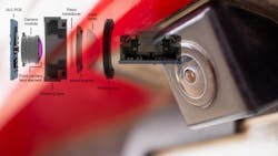
One problem with building a ULC system is the difficulty of bonding a piezoelectric transducer directly to glass. Texas Instruments solved this problem with a system that employs a bracket that interfaces a ring-shaped transducer to the glass without any direct glass-to-transducer contact. The ring transducer takes up little space, enabling what TI calls its lens cover system (LCS) to sit compactly over the camera lens. A curved LCS (Fig. 3) provides a wide field of view with minimal optical distortion.
As a compact alternative to using a lens cover, a ULC system can directly drive the camera lens front element. However, because lens elements aren’t uniformly thick, establishing adequate standing waves can be difficult. In addition, an approach that directly drives a lens element could present alignment challenges in manufacturing, whereas the LCS is amenable to an easily scalable production process.
ULC Processor
Interfacing the transducer to the lens is just one aspect of ULC design. Another key is determining exactly what excitation to apply to establish the appropriate standing-wave modes.
To that end, TI developed proprietary algorithms for ultrasonic lens cleaning. Those algorithms run on its ULC1001 configurable digital signal processor, which includes current- and voltage-sense amplifiers and an analog-to-digital converter. The device can be configured to detect contaminants and faults as well as temperature to prevent the transducers from overheating.
The ULC1001 also includes a pulse-width modulator, which creates the frequencies necessary to establish the appropriate standing-wave modes in the lens or lens cover. It implements its temperature detection, lens-fault detection, contamination detection, and ultrasonic-burst execution functions using a state-machine architecture (Fig. 4).
The ULC1001’s PWM output serves as an input to TI’s DRV2901 lens-cleaner transducer driver, which amplifies ULC1001’s PWM output. The DRV2901 requires only simple passive LC demodulation filters to deliver high-quality, high-efficiency outputs to the piezoelectric transducers while maintaining low noise levels to facilitate EMI compliance.
Conclusion
TI’s ULC1001 and DRV2901 enable compact camera systems to employ precisely controlled ultrasound vibrations to rapidly clear contaminants such as rain and dirt from lens surfaces. ULC can serve in manufacturing, automotive, robotics, smart agriculture, and any other application where a camera is subject to contamination.


