Members can download this article in PDF format.
Industry 4.0 is driving an explosion of diagnostic data on the factory floor, enabling systems to become smarter and equipment to become more reliable through predictive maintenance. One area lacking in data, however, is the 24-V dc power-distribution system, which carries power to programmable-logic controllers (PLCs), robots, machine tools, and other industrial equipment.
Troubleshooting the 24-V dc power system often requires a tedious process of manually checking LED indicators and disassembling power modules, all of which extends downtime and reduces productivity.
Adding Current Sensing
Data on the currents flowing in the power-distribution system could help greatly in diagnosing problems. Such data could pinpoint overloads as well as short and open circuits, and it could help identify aging mechanical systems that require maintenance or replacement.
Traditionally, though, such current sensing required analog-to-digital converters (ADCs), isolation barriers, and high-side switches with current-monitoring capability. That combination could be expensive and difficult to implement, especially if you need multiple ADC channels and associated routing cables.
An alternative that leads to simpler installation, lower cost, and lower power consumption is to use high-side switches with current sensing and an integrated ADC. Texas Instruments’ TPS274C65 packs four high-side switches, an ADC, and sensors into a 6- × 6-mm quad flat no-lead package. The combination reduces power dissipation by 38% compared to conventional implementations of similar functionality.
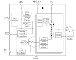
In addition to sensing current, the device can sense the temperature of its internal metal-oxide-semiconductor field-effect transistors (MOSFETs) as well as input and output voltages. An integrated multiplexer connects the ADC to each sensor as needed, minimizing the requirement for external wiring.
The implementation allows for local and remote analysis. The TPS274C65 can directly drive eight LEDs to indicate fault status near the equipment being monitored, and a Serial Peripheral Interface (SPI) handles communication with the system microcontroller through a digital isolator, such as a member of the TI ISO77xx family. The microcontroller, in turn, can relay the status over a factory- or corporate-wide network.
The TPS274C65 implementation provides several benefits in addition to locating immediate faults. For example, it enables collection and storage of data before a failure occurs, which can be analyzed to schedule predictive maintenance. Say a motor or solenoid’s load-current profile had begun degrading days or weeks before a failure. Its load profile could be monitored in the future for similar degradation, enabling a scheduled replacement or repair with minimal disruption and downtime.
Device Details
The TPS274C65 (Fig. 1) includes several features that make it suitable for factory-automation applications. Its four switches have 65-mΩ RDS(ON) resistance values to minimize power dissipation even while providing large output currents into resistive, inductive, or capacitive loads. Current limit is adjustable from 300 mA to 2.6 A.
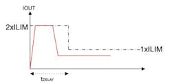
The device’s dual-stage transient and dc current-limit capability provides the flexibility necessary to accommodate high inrush currents when turning on capacitive loads. Figure 2 shows the inrush current limit set to twice the dc current limit for the time period tDELAY.
The device’s SPI port operates up to 10 MHz and has three logic inputs (clock, chip select, and serial data in) and one output (serial data out). It can operate in both simple daisy-chain and addressable SPI modes. The latter simplifies diagnostics and configuration.
The SPI mode enables on/off control of the four switches, and it can disable diagnostic functions to reduce quiescent current when the device isn’t active. SPI mode also allows you to set the current-limit thresholds and access the output current, output voltage, and temperature for each switch.
Getting Started with an Evaluation Module
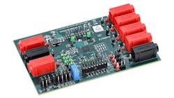
To help you get started, TI offers the TPS274C65EVM evaluation module (Fig. 3), which includes two TPS274C65 devices configured in the addressable SPI mode, an integrated TM4C123 Arm Cortex-M4F microcontroller with a USB host interface, and an ISO7763DWR digital isolator that provides reinforced isolation from high-voltage rails. It also comes with firmware written in embedded C for the microcontroller. You can customize the firmware using an Arm debugger.
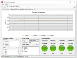
In addition, TPS274C65 Configurator Software, a lightweight Windows host GUI, enables device configuration and monitoring. The GUI lets you change all register settings of both TPS274C65 devices to configure the current limit and other functions. It also lets you record load current, FET temperature, and input/output voltage and display the data in graphical format. In addition, the GUI supports fault monitoring and reporting for all fault conditions.
When you open the configurator, you will need to use the dropdown box across the top of the screen to select which of the two TPS274C65 devices in the evaluation module you want to view. Figure 4 shows Device #1 selected; it’s carrying 1.27 A on channel 1, and no faults appear on any of the four channels.
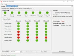
The software offers other views as well. The fault view in Figure 5, for example, shows shorts, opens, overcurrent, and reverse-current conditions as well as thermal shutdown status for all four switches in the module’s device 1.
Conclusion
High-side switches with integrated ADCs and current-sensing capabilities provide a cost-effective, easy-to-implement way of measuring currents in 24-V dc power-distribution systems in industrial environments. TI’s TPS274C65 incorporates four high-side switches, sensors, and an ADC to help you quickly locate faults, schedule predictive maintenance, and minimize factory downtime. And the company offers an evaluation module with two TPS274C65 devices and a microcontroller to help you get started on a successful design.

