Advanced Traction-Inverter Systems Extend Driving Range
Members can download this article in PDF format.
The efficiency of traction inverters at the heart of electric vehicles (EVs) directly impacts the available operating range of the vehicle on a single charge. In addition, efficiency, safety, and reliability are key factors in EV design.
To meet all three requirements, these inverters depend on various smoothly operating components and subsystems, including silicon-carbide (SiC) switches, microcontroller units (MCUs), low-voltage bias supplies, high-voltage bias supplies, DC link active-discharge circuitry, motor position sensors, isolated voltage and current sensors, and isolated gate drivers.
Architectures and Components
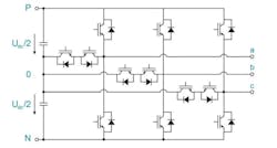
Traction-inverter architectures are evolving to boost efficiency and power while minimizing electromagnetic interference (EMI). Currently, the three-level T-type neutral-point-clamped (TNPC) architecture (Fig. 1) is gaining ground because it supports power levels beyond 300 kW and minimizes harmonic distortion, allowing for the use of smaller EMI filters.
Other trends in traction inverters include increasing the ISO 26262 Safety Integrity Level (ASIL) from C to the more stringent D, shifting toward 800-V technology, replacing resolvers with inductive position-sensing technology, and implementing adjustable gate-drive strength and active discharge functionality into gate-driver ICs.
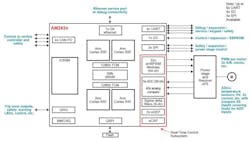
MCUs are key components for traction inverters, and Texas Instruments offers several suitable for EV use. Among them are members of its Sitara family, which feature an Arm-based architecture and incorporate ASIL D functional safety. Figure 2 shows an AM2634-Q1 Sitara MCU in a traction-inverter application.
A traction inverter generally requires a low-voltage bias supply that connects to a low-voltage source such as a 12-V battery. TI offers several products to fulfill that function.
First, the UCC14240-Q1 isolated DC-DC converter module delivers 1.5 W of output power and provides ±1.3% output voltage regulation. The UCC25800-Q1 inductor-inductor-capacitor resonant converter features ultra-low EMI emissions, and the SN6507-Q1 high-frequency push-pull transformer driver comes equipped with integrated MOSFETs. Finally, the LM2518x-Q1 family of primary-side-regulated (PSR) flyback converters has integrated power switches that can operate over a 4.5- to 42-V input voltage range.
A traction inverter may also require a high-voltage bias supply to establish a redundant power source for powering up safety-relevant circuits. TI presents several reference designs for this function. One, the TIDA-01505 automotive flyback reference design, generates a 15-V, 4-A output from a 40-V to 1-kV input. And the company’s PMP22817 reference design describes a bias supply that provides the high isolation necessary for 800-V DC applications.
Safety considerations also require that traction inverters include a DC-link active-discharge function. This function must discharge the DC-link capacitor at vehicle key-off or during an emergency. The subsystem implementing this function must meet ASIL D as well as operate independently of the MCU in the event of MCU failure.
Several products from TI can be used to implement this function, including the TPSI3050-Q1 reinforced isolated switch driver. It has an integrated 10-V gate supply that drives the discharge power switches with no need for a secondary bias supply.
Sensible Sensors
Inverters also need several sensors, including rotor position sensors to provide feedback to the speed and torque control loops. Although inductive position-sensing technology is making inroads, these sensors have traditionally been variable-reluctance resolvers, whose primary windings require an excitation voltage generated through excitation amplifiers such as TI’s ALM2403-Q1 or TAS5431-Q1.
A position-sensor interface IC takes the resolver differential sine and cosine output signals and applies them to the MCU for processing. TI’s TIDA-01527 reference design describes a discrete resolver front-end that provides ±0.1-degree accuracy.
In addition, traction inverters require isolated sensors for voltage and current measurements such as DC-link voltages and motor phase currents. TI’s AMC1311B-Q1 and AMC1351-Q1 isolated amplifiers and AMC1305-Q1 isolated modulators help to achieve high accuracy, high bandwidth, low latency, and low temperature drift for such applications. The products offer both basic and reinforced levels of isolation and include a silicon-dioxide capacitive isolation barrier to support a high level of magnetic-field immunity.
Variable Gate-Drive Strength
In traction inverters, varying the gate-drive current controls the slew rate of the SiC power switches. Fast switching generally implies higher efficiency, but the accompanying high slew rates can cause voltage overshoots. The TI UCC5880-Q1 gate driver with real-time variable gate-drive strength helps optimize efficiency while minimizing overshoot to keep the powertrain cool and running.
For a fully charged battery, the UCC5880-Q1 applies weak gate-drive strength to reduce voltage overshoot and improve the SiC switches’ reliability. As the battery discharges, the device applies strong gate-drive strength to reduce SiC switching losses and significantly increase efficiency. The efficiency gain can be significant—real-world drive-log speed and acceleration data show the increased powertrain efficiency can add miles of driving range per battery charge.
Inverter Reference Design
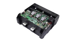
To help you get started on a traction-inverter project, Texas Instruments and Wolfspeed developed the TIDM-02014 800-V, 300-kW SiC-based traction-inverter system reference design. The design demonstrates how a TI UCC5880-Q1 high-performance isolated gate driver with real-time variable gate-drive strength drives a Wolfspeed SiC power module, minimizing voltage overshoot and optimizing efficiency (Fig. 3).
The isolated gate driver coupled with TI’s isolated bias supply significantly reduces the PCB size and eliminates more than 30 discrete components, thereby improving system power density. TI’s high-performance MCUs in the reference design feature tightly integrated, real-time peripherals to enable effective traction-motor control even at speeds greater than 20,000 RPM. A fast current-loop implementation helps minimize motor torque ripple and provides smooth speed-torque profiles.
In addition to the UCC5880-Q1, the reference design employs AM2634-Q1 MCUs, CAN and CAN FD transceivers, isolated DC-DC converter modules with integrated transformers, and reinforced isolated amplifiers.
Conclusion
As EV powertrain technology becomes more complex, efficiency, reliability, and safety become critical. Choosing the right components can help you boost all three. TI offers a complete portfolio of products for traction inverters, and it provides reference designs that can help get you off to a smooth start.


