What’s All This Multiplier-Divider Stuff, Anyhow?
Download Volume 3 of the Bob Pease eBook series.
A few weeks ago, an engineer knocked on the front of my cubicle and asked, “Can you recommend a good design for a multiplier-divider?” I just happened to have my Linear Apps book open to AN-31, so I said, “Like this one?” (see http://cds.linear.com/docs/Application%20Note/an31.pdf)
She said, “No, not exactly. That runs on ±15-V supplies, and I need one to run on +4 V.” Oh. So the engineer showed me the specs she needed: IOut = (I1/I2) × I3. The I1 and I2 would cover barely an octave, and I2 could be bigger than or smaller than I1. And I3 would be just a few µA.
After pinning down the process and a few more details, I told her, “Go away, and see what I got for you tomorrow.”
Time to design
Anyhow, I cobbled together this basic idea. It was still adding and subtracting logs, but it didn’t need so many op amps—like one instead of four. A week later, I asked her how it was coming. She replied, “Oh, we decided we didn’t really need that....” I explained, “Well, I gave that to you, and if you aren’t going to use it, I want it back.” So I took it back. And here it is (see the figure).
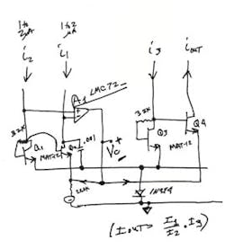
To take a ratio of I1 to I2, we just need to put those currents through a pair of well-matched NPNs, such as Q1 and Q2. I put in a servo amplifier A1 to establish a control voltage, VC, which will be 18 mV per octave at room temp. VC can be positive if I1 is bigger than I2—or smaller if vice versa. This VC is also applied to Q3 and Q4. The ratio factor established by VC will scale IOut as needed. Piece of cake.
Normally we would like to use the National LM394 for the matched pairs. But since some foolish people obsoleted them, we’ll just the next best thing, the MAT-12.
Now, this multiplier as shown is designed around some tightly matched transistors and one real op amp. If this was being constructed in a biCMOS IC process, the discrete matched NPNs could easily be replaced by some well-matched common-centroid NPNs with (presumably) low offset, and the op amp could be replaced by a P-channel matched pair, running as a differential amplifier. Still, the idea is the same: A simple servo, to generate VC....
Have I built this? Not yet. But that’s not a big deal. Circuits like this are very easy to test out with back-of-envelope Spice. It will work perfectly.
Bob’s Mailbox: Steering Lock-Ups
Hi Bob,
I have a 1991 Chevy S-10 pickup truck with automatic transmission that locks up. When one turns the key all the way toward off and does not pull the key out, the steering wheel will still lock up. I tried this while driving and learned quickly how it behaves. Just to be sure, I went out and tried it in my driveway and it indeed locks up.
Full disclosure: the test while driving was with me driving and my daughter as a passenger. I wanted to demonstrate and make the point to her that if the engine stalls, you will lose power steering. But even though the steering wheel is harder to turn, it still works. To my surprise, it locked while doing 45 mph. I quickly turned it back on before I got into real trouble.
-Jim Sylivant
That was a first-class demonstration! I think your daughter got a fine education. One of the best.
But if you only turned it 20°, until the engine died, it wouldn’t lock up, right? In a stick shift, just kick it out of gear when you turn off the key, and when you turn the key back, you’ll be safe.
Best regards. /rap
About the Author

Bob Pease
Bob obtained a BSEE from MIT in 1961 and was a staff scientist at National Semiconductor Corp., Santa Clara, CA, for many years. He was a well known and long time contributing editor to Electronic Design.
We also have a number of PDF eBooks by Bob that members can download from the Electronic Design Members Library.
Comment About the Article
To join the conversation, and become an exclusive member of Electronic Design, create an account today!

Leaders relevant to this article: