Download this article in .PDF format
Most companies used to be concerned that models would reveal their secret intellectual property (IP). But now that it’s possible to encode the details, most analog semiconductor companies provide Spice models of their devices. In fact, several companies offer free downloadable Spice simulators or “Spice-like” software that provides for schematic capture and simulation.
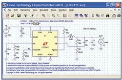
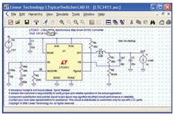
For more than 15 years, Linear Technology has offered LTspice, internally developed and still maintained by Mike Engelhardt (Fig. 1). More than half a million copies have been downloaded from Linear’s site (www.linear.com/designtools/software/#LTspice).
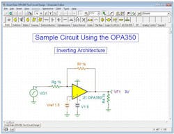
Texas Instruments provides downloadable TINA-TI, a customized version of DesignSoft’s TINA Design Suite, which offers design capture, simulation, and analysis capabilities that are similar to Spice (Fig. 2). A complete version of TINA Design Suite provides additional capabilities for real-time testing of analog, digital, VHDL, MCU, and mixed electronic circuits and their printed-circuit board (PCB) layouts. Users also can analyze switched-mode power supplies (SMPS), RF, communication, and optoelectronic circuits, as well as generate and debug microcontroller code to run the simulated circuit under MCU control.
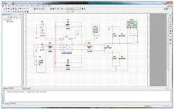
In a similar reduced feature-set arrangement, Analog Devices offers a downloadable version of National Instruments’ MultiSim tool called MultiSim Component Evaluator – Analog Devices Edition (Fig. 3). Although it provides full Spice-like design capture, simulation, and analysis, the download license agreement says the tool may not be used in a university teaching environment by any student or faculty member.
Intersil now offers iSim:PE presently exclusively for Intersil’s op amps and power management devices (Fig. 4). Like TI’s WEBENCH, which was developed at National Semiconductor before it was acquired by TI, it creates custom design solutions for specific conditions based on the company’s chips, rather than allowing an engineer to simulate designs ad-hoc. For that matter, Analog Devices’ Circuits from the Lab is an extensive library of bench-proven designs.
In contrast to the Spice-like tools, none of these latter resources provide the same degree of flexibility. On the other hand, they can provide usable results more quickly, and they don’t allow users to make the kinds of mistakes that used to annoy Bob Pease (see “What Did Bob Pease Really Think About Spice?").
Spice’s History
Before there was spice, an engineer would draw a circuit, manually perform a nodal analysis using Kirchhoff’s current laws, write down the matrix of equations using Laplace transforms, solve the mesh, and extract the actual circuit behavior using reverse transforms. That wasn’t too bad if you weren’t an EE undergrad doing it all from scratch, but it was a task that cried out for a computer-based solution.
Based on prior classified work in nuclear engineering, Laurence Nagel, a UC Berkeley grad student working under Professor Donald Pederson, developed SPICE1 in FORTRAN and unveiled it in 1973. SPICE1 evolved into the more usable SPICE3 in 1975. The need to run these programs on mainframes limited their utility until the first version written in C, SPICE3, was unveiled in 1989. It ran under BSD UNIX.
These releases were IC design tools that ran on mainframes and workstations. PSpice, an analog circuit and digital logic simulation program for Microsoft Windows, appeared in 1984.It ran under BSD UNIX.
These releases were IC design tools that ran on mainframes and workstations. PSpice, an analog circuit and digital logic simulation program for Microsoft Windows, appeared in 1984. Berkeley made PSpice available for PCs running Windows 1984, democratizing the use of the program. The next task was to make it easier to use, and Mike Engelhardt at Linear Technology got that assignment in the late 1990s. It’s now up to version IV. Its evolution makes for an intriguing tale.
How Engelhardt Made LTspice
Engelhardt is essentially the godfather of Linear Technology’s freeware LTspice, and he has been supporting it and making it faster for 15 years. It all started because Bob Swanson and Bob Dobkin asked for a promotional tool. They got rather more than they bargained for because Engelhardt is the kind of engineer who obsesses about doing the job as thoroughly as possible. In this case, he wanted to make LTspice the world’s fastest.
He also wanted to give Linear’s chip designers the opportunity to make the best models. He points to Linear’s current-mode switching supplies as an example. “A current-mode switch-mode power supply is basically a glorified flip-flop,” he begins. “Something sets the flop, turns on a power switch, and a current is monitored, and when a condition is met, the thing is reset.” As long as the designer gets that flip-flop working correctly, gets the “reset” condition correctly, and has the right transfer function between the compensation of voltage and peak current, “basically everything else is a detail.”
This approach led Engelhardt to conclude that behavioral models are more useful than transistor-level models. “When we make analog models, we can avoid a bunch of numerical difficulties. When we get done setting up the system simultaneous equations that need to be solved, we have many fewer non-zero elements,” he says. That makes it possible to solve the equations more rapidly.
Sometimes, this comes down to a black-box approach. Returning to that switching-supply example, Engelhardt says, “The main flip-flop of current-mode switcher is basically about a dozen gates. That’s because you have to accommodate a maximum duty cycle and you want to set it with an edge and reset it with an analog condition.” In terms of a fine-granularity model, implementation typically takes about a dozen gates. Instead of modeling that, Linear has a native circuit element that does that, and its behavioral model simulates faster.
“World’s Fastest Spice”
Engelhardt says his approach to accelerating Spice evolved in an interesting fashion, and it required breaking some rules. “In the ’70s when you were writing a numerical solver, and you were being disciplined about it, you would always keep firmly in mind that the fastest way to complete something was to not compute it all but to put it in a lookup table,” he says, but that wasn’t for him.
“That’s the worst thing you can do. The computer CPU is hundreds of times faster than memory. Every time you use a lookup table, you have to fire those transistors in the RAM. You have to keep everything in cache,” he says.
Surprisingly for someone who is talking about designing a Spice to run on PCs, Engelhardt turned to Seymour Cray for inspiration. Engelhardt says that matrix solving is a classic application of parallel processing.
“The Cray was about being able to take a row of a matrix, multiplying it all by one number and subtracting it from a number of rows,” he says. Initially, in fact, Engelhardt had written a multi-threaded matrix solver and found it hundreds of times slower than a single-threaded matrix solver. So, he analyzed the actual time required to execute all of the instructions.
He found that the timing of the different threads was, in a sense, chaotic. It turns out to be better to use one thread than multiple threads because the timing between threads means it’s impossible to get any speed up from using multiple threads. That insight sent him to the literature about multi-threaded sparse-matrix solvers, which confirmed what he was finding out.
“You can implement a multi-threaded solver that runs faster than a single-threaded solver if the matrix is exceedingly this sparse. But to solve the circuit matrix for a big IC, only a few parts out of a thousand are non-zero,” he says. One problem was selling that concept in an engineering environment that expects a multi-threaded solver, so he told people that it was a multi-threaded solver, but the matrix itself was single threaded.
That wasn’t the end, though. He then thought he could write a faster matrix solver. Engelhardt’s next discovery was related to the number of clock cycles it takes to perform a floating-point operation. Benchmarking the kind of 3-GHz processors that were in common use, he figured each clock was 300 ps, and three of them were required to execute one floating-point operation.
“After the operation has been completed, if there’s a long pipeline, you’ve got to wait to give the result to the processor at the end of the pipeline,” he says. With Engelhardt’s approach, the processor has to sit there and twiddle its thumbs for 900 ps before it can multiply two floating-point numbers to yield a 64-bit accurate result. He reckons that if you’re counting floating-point operations, this makes a multithreaded architecture run at probably something like only 10% of its theoretical speed. So, he found a way to fix that—another technique based on the wise use of memory. The only important thing, he says, is how well you use the cache.
“When you’re coding in a high-level language, much of the time when we refer to ‘X,’ it’s not X, it’s the address of X. And, the programming language doesn’t know where X is stored. So you have to ping the transistors on the motherboard a few times to get the actual bit pattern that’s your double-position number. And that’s unavoidable,” he explains.
But here’s the trick: “After you know where your data is, if you to look at all your addresses, at that point you could call an assembly language program that would access the data itself, keeping the pipeline full. And that’s what LTspice does.”
Effectively, after it loads all the data, LTspice finds a strategy for pivoting the matrix and solving it. Then it accesses the assembly language program, assembles it, links it, and just calls each address to solve the matrix. “And that sped up the process by a factor of three,” he says.
When experienced circuit designers began to download LTspice and use it, they immediately noticed the difference from PSpice. They didn’t see it immediately in terms of efficiency, but it was noticeably faster. However, Engelhardt also notes that LTspice is for circuit design. It’s not intended to compete with an IC design tool such as Cadence’s HSPICE. On the other hand, it’s free, versus $1500.
Of course, the implementation of the modeling is only part of the story. The other part is the models. Engelhardt says that modeling power MOSFETs is tricky. “Power MOSFETs are hard to simulate in most Spice programs because a power MOSFET is a vertical structure. It has a drain on the back of the die. In contrast, in modeling an IC, everything is lateral and on the same side of the silicon,” he says.
“We made a vertical MOSFET model where the gate and drain can be different sizes, and the channel is in between them, with the capacitance between the gate and the drain being dependent on whether the channel is enhancement or depletion. That charge model doesn’t exist in other Spice programs,” he says.
He says it’s important to have that capability. The need for it became obvious when it became clear that with other Spice programs, “Switching waveforms from power MOSFETs didn’t match what you see on the bench, and that’s because this gate-drain capacitance introduces a Miller effect that dominates the switching characteristics,” he says.
TI-TINA
At TI, John Rice agrees with Engelhardt about the challenges of modeling switching supplies and MOSFETs. “Looking at a switching regulator with its fast-switching edges, it becomes a burden on the Spice analysis engine to solve for all of the nodal voltages and currents, particularly if you have a lot of nodes,” he says. Tools such as TINA can simulate converters operating at megahertz speed in seconds, instead of the tens of minutes it took in the early days of Spice.
On the subject of MOSFETs, Rice says that TINA allows users to model things like the switching characteristics of the devices, enabling designers to look at the plateau region to assess switching losses, going so far as to set the different ambient temperatures. He notes that the issue there is not the capability itself, but the speed of the execution, as that capability for MOSFET models was established as early as SPICE3.
Rice shares Bob Pease’s opinion that one of the most important things that anybody who sets out to conduct simulation needs to understand is that there’s no substitute for understanding what one is doing, both at the circuit level and at the simulation level.
“You need to understand the topology that you’re simulating. Whether it’s a simple fourth order filter or it’s a switching regulator or even a microprocessor, you have to have a basic idea of what you’re going to get so you can use that to validate the circuit or the simulation,” Rice says.
“If you don’t, Spice will lie to you.”
Rice cites a switching regulator, where it’s relatively simple to mechanically calculate where the peak currents are in the various magnetic components from the duty cycle. “When I run my simulation, if those don’t match or at least come close, then I know something has gone awry,” he says.
Rice also brought up model encryption, which gives chip vendors the confidence they can release models of their parts that will not reveal their IP to competitors. “We encrypt our models to protect our IP,” Rice says. On one TINA display, for example, he notes a model in which the IP is defined as various subcircuits. “It has all of the various nodes, but the actual constructs are encrypted,” he says.
He also points out a macro for an error amplifier. “The macro is defined in terms of how much current it can source, its bandwidth, and so forth,” he says. Elsewhere, an oscillator is modeled as a window comparator. “These behavioral constructs are higher-level abstractions of the transistors that are used to build the integrated circuit. But in the simulation, the models actually run faster, and they run with sufficient fidelity to emulate typical behavior.”
Roll Your Own Models
But why leave it to the chip companies to create all the Spice models? At this year’s Texas Instruments Power Supply Design Seminars, Rice led a seminar called “Accelerating Power Supply Compliance to Specification.” He described an upcoming paper in which he offers a practical approach for developing and implementing a Spice-based power-supply analysis and confirming that analysis through advanced measurement techniques.
Most models that can be downloaded from chipmakers just reflect data-sheet “typical” behavior. To go beyond that, to develop a worst-case analysis, or an analysis under extreme operating conditions, designers have to know how to build their own model.
Rice says the analysis part of his paper goes through a step-by-step process of building a behavioral model of a switching regulator. “I tear down the whole IC from the block diagram in the datasheet and I build each subcomponent, the modulator, the error amplifier, the multi-mode type control, the flip-flop, the MOSFET, and the internal MOSFET,” he says.
“I actually devised 34 references that talk about Spice and how models are built and the algorithms, how Spice uses numerical integration to create linear companion models and how the basic algorithm works,” he says.
Dynamic Conditions
Rice is enthusiastic about TINA’s ability to run dynamic simulations. In the paper, he describes a circuit he created for an automotive customer that addresses “start-stop,” the new paradigm in today’s cars in which the internal combustion engine shuts off at stoplights and when the car is stuck in traffic. When the car restarts, it is necessary to stabilize the voltage according to a profile that the carmaker has defined from empirical testing, accounting for cold-crank and warm-crank conditions, as well as changes over battery life and similar factors.
This is a multi-variable problem. Rice demonstrates a transient analysis that executes in less than a minute. In fact, the simulation that he built for the seminar runs at 1.2 MHz and completes startup to steady state in 10 seconds. Just five years ago, it might have taken 30 minutes to run on a laptop. That’s what TINA is capable of, but it requires an understanding of how to build a Spice model effectively, which was the point of the paper in the seminar.
Reviewing Pitfalls
According to Michael Steffes, Intersil remodeled all of its parts about two years ago, adding realistic parasitics. He has been trying different sorts of industry-standard circuit topologies and checking to see whether under different conditions they show the performance characteristics one would see on a real board.
“There are a couple of key op-amp parasitics that are not necessarily captured in all vendor models. One example is input parasitic capacitance, which some people don’t care about because they aren’t interested in the shape of the frequency response at higher frequencies,” he says, looking outside of Intersil.
“But if you’re doing active-filter tools, for Sallen-Key filters for instance, if you’re using really large Rs and smaller Cs, that parasitic can shift your response pretty quickly, as you look at higher frequencies,” he explains.
“Another example of significant op-amp parasitics is open-loop output impedance. That plays a very important role in terms of response flatness,” he says, adding that the expectation of an ideal voltage output source is unrealistic and real circuits may experience instabilities that were never seen in the simulation.
“Also, designers who have done real breadboarding know from hard experience that, if you put a capacitor on an op-amp output pin, for certain part numbers and for parts with certain speed ranges, they’re likely to get into some sort of peaking trouble. The problem is that if your model incorporates a pure voltage output, you will never see it in stimulation,” he says. “The theme of a lot of what we’ve been doing at Intersil is to guarantee no surprises from simulation to board.”
Steffes also notes that many rail-to-rail low-power parts, especially chopper-stabilized amps, have a real load dependence in their open-loop characteristics. This needs to be embodied in the macro model.
“There are also output-clipping and overdrive-recovery issues that are rarely modeled at a fine level of detail. I mean, they’ll clip if you try driving the input beyond the supplies in most models, but recovery from overdrive performance may not always be picked up,” he says.
Despite every supplier’s best intentions, there are pitfalls. “I’m not sure if an automated tool will always keep you out of trouble. There needs to be some vetting of the actual layout so that bad things don’t happen,” Steffes says, noting an engineer who recently came to him.
“‘Hey, I got this board and it looks like it’s okay, but I’m picking up these oscillations at gigahertz frequencies. What’s happening?’” he says the engineer asked him.
“And we looked at it and there’s a 50-Ω terminator on the board, but it’s at a board edge. And then there’s probably about an 8-cm trace to the input that is just a trace,” Steffes says. “So the input transistors are 10-GHz transistors and they’re seeing this big inductor before it gets back to a termination. So, it’s finding a frequency to oscillate at. Everybody needs to get rules into their layout tools to prevent mistakes like that from occurring.”
About the Author

Don Tuite
Don Tuite (retired) writes about Analog and Power issues for Electronic Design’s magazine and website. He has a BSEE and an M.S in Technical Communication, and has worked for companies in aerospace, broadcasting, test equipment, semiconductors, publishing, and media relations, focusing on developing insights that link technology, business, and communications. Don is also a ham radio operator (NR7X), private pilot, and motorcycle rider, and he’s not half bad on the 5-string banjo.


