Download this article in PDF format.
A comparator is a great circuit because it provides a near ideal transition between the analog and digital domains. The comparator looks at two linear input signals and gives a digital output that’s either high or low depending on whether one input is above or below the other. Simple, but widely useful.
If you need this type of circuit in your design, it’s best to use an IC comparator that was designed for such applications. However, most designers know that a standard op amp can be used as a comparator. And in some designs, an extra op amp may be available, thus avoiding any extra cost or need for more space.
Chances are that the resulting op-amp comparator will probably not deliver the desired optimum performance. This amateur design error can result in more debugging and redesign time than planned. The best advice is that if you need a comparator, use an IC comparator to avoid problems and achieve the best possible outcome.
Sponsored Resources:
- TI Precision Labs - Op Amps: Comparator Applications
- Op Amps used as Comparators—is it okay?
- Comparators—what’s all the chatter?
What are the Real Differences Between an Op Amp and Comparator?
The main differences between these two include:
- The built-in phase compensation needed to stabilize an op amp usually makes the device too slow for comparator switching operations.
- The input stages of an op amp are typically protected with diodes or other transistors that often compromise its use as a comparator.
- The output stage of an op amp is designed for linear operation. The output with bipolar power supplies swings positive and negative, and must be conditioned for use in digital circuits.
- A real comparator output stage is designed for saturated operation and matches common digital logic levels. The output is often of the open-collector (drain) type.
- An op amp is usually configured with external input and feedback resistors to set the gain and other characteristics of the circuit. A comparator usually runs open loop; i.e., no feedback.
- Comparators offer shorter delay times and a very high slew rate compared to an op amp.
Despite what may appear as similarities, the two circuits are different animals with different applications.
So is it okay to use an op amp as a comparator? Maybe. Many engineers have used an op amp as a comparator. This is often done when you only need one comparator and you have a “spare” op amp in a quad op-amp package. The phase compensation required for stable op-amp operation means that it will be very slow as a comparator, but if speed requirements are modest, the op amp may suffice. Sometimes this approach works, but other times it falls short.
Comparator Operation
1. Here’s an op amp connected as an inverter (a), and its input-output transfer curve (b).
One way to look at the operation of a comparator is to examine the basic op-amp configuration shown in Figure 1a. The amplifier has very high open-loop gain (AOL >> 1000). What it amplifies is the difference between the two inputs V1 and V2. The output is:
Vo = AOL (V2 – V1)
Because of the high gain, it doesn’t take much of a differential input signal (V2 – V1) to drive the output to either the positive or negative power rail. For example, if the supplies are ±5 V, and the open-loop gain is 100,000, a differential input of 5/100,000 = 50 µV or more will drive the output to the rail. Figure 1b depicts the input-output transfer curve.
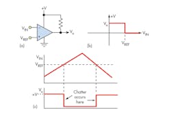
2. Shown is an inverting comparator with typical inputs (a), its transfer curve (b) and input/output signals (c).
A true comparator operates from a single supply that commonly also operates the digital logic. The output is connected to a pull-up resistor to the supply rail (Fig. 2a). The inputs to the comparator are the reference (VREF) and the signal that’s compared to the reference (VIN). Either of the two inputs can be connected to the reference or input signal. A common arrangement is a fixed reference voltage value and a varying input signal. Two common versions are the inverting and non-inverting configurations:
- Inverting form: VIN connects to the amplifier inverting (−) input and VREF connects to the non-inverting (+) input (Fig. 2). If VIN > VREF, the output goes low. If VIN < VREF, the output goes high.
- Non-inverting form: (Inputs reversed in Fig. 2) VIN connects to the amplifier non-inverting (+) input and VREF connects to the inverting (−) input. If VIN > VREF, the output goes high. If VIN < VREF, the output goes low.
Fig. 2 shows an inverting arrangement with a fixed dc reference and a triangle wave input (Fig. 2c). With the input below the threshold, the output is high (see transfer curve in Fig. 2b). As the input exceeds the reference, the output switches low. Later, as the input decreases, the output again switches as the threshold is passed.
Dealing with Noise
One problem that often occurs is the noise or multiple short transitions on the output at the threshold points. This so-called chatter occurs when the input is varying slowly and can cause false triggering in an application. Even with very clean input voltages, comparators have their own noise—like an op amp. They also sometimes make noise when the output slams from one rail to another, reverberating through the supply or output circuitry back to the input.
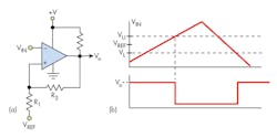
3. A comparator with hysteresis (a) can eliminate chatter at the transition points (b).
One way to overcome this is to use hysteresis (Fig. 3). The reference is applied via two resistors that provide regenerative or positive feedback that speeds up the switching and virtually eliminates the chatter.
What the hysteresis does is to establish upper (VU) and lower (VL) trip point voltages around the reference level. The small window or dead zone keeps the output clean with no chatter. The values of R1 and R2 set the trip points that can be calculated with these equations:
VU = +V [R1/(R1 + R2)] + VREF [R2/(R1 + R2)]
VL = VREF [R2/(R1 + R2)]
Learn More
If you want to know more about the op amp as a comparator, check out the Texas Instruments Precision Labs training series on op amps. Lesson 14 covers the functionality of the comparator and its key dc and ac specifications; how to apply hysteresis to protect against comparator input noise; and the pros and cons of using op amps as comparators.
Sponsored Resources:
About the Author

Lou Frenzel
Technical Contributing Editor
Lou Frenzel is a Contributing Technology Editor for Electronic Design Magazine where he writes articles and the blog Communique and other online material on the wireless, networking, and communications sectors. Lou interviews executives and engineers, attends conferences, and researches multiple areas. Lou has been writing in some capacity for ED since 2000.
Lou has 25+ years experience in the electronics industry as an engineer and manager. He has held VP level positions with Heathkit, McGraw Hill, and has 9 years of college teaching experience. Lou holds a bachelor’s degree from the University of Houston and a master’s degree from the University of Maryland. He is author of 28 books on computer and electronic subjects and lives in Bulverde, TX with his wife Joan. His website is www.loufrenzel.com.


