Enhanced VLED Driver Updates JFET Constant-Current Source

Download this article in PDF format.
High-brightness visible-light LEDs (VLEDs) require a constant-current source. This simple, RFI-free circuit takes advantage of the normally-on properties of the new, high-power depletion-mode (Dmode) MOSFETs to provide this source.
Historically, the simplest method for driving a load such as an LED uses a fixed or variable resistance between the power source and the load (Fig. 1). While low cost, the current doesn’t remain constant, but varies with supply voltage and temperature rise with current load. The poor efficiency can be improved by replacing the passive resistor with an active component or circuit whose impedance automatically adjusts to maintain a specific value of current, even with varying supply voltage and/or heavy loads.
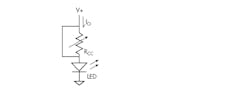
1. Using a current-limiting resistor is the simplest to control the current through an LED.
Constant-current sources constructed using the normally-on properties of a JFET or Dmode FETs are restricted to very low power levels. These devices are controlled by voltage rather than current as in the older bipolar junction transistors. While small-signal JFETs are available in both p and n types, the new Dmode FETs are able to manage the heavy currents required by the new blue and white VLEDs for proper operation, but are currently restricted to n-types.
In a traditional Dmode FET constant-current circuit (Fig. 2), only the FET and a resistor (fixed or variable) is required. Current flowing through the FET generates a voltage across the resistor with a value chosen to generate the level of pinch-off voltage (VGS(off)) necessary to provide the desired constant current (Io). The two-terminal CCS allows the load to be arbitrarily connected to either the drain or, most commonly, the gate terminal as shown.
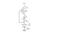
2. A better approach is to use a FET as a constant-current source.
The IXTP3N50D2 Dmode FET from IXYS Corp. powers a 5-W white VLED such as the LZI-00NW05 from LEDengin (190 lumens at 1 A); the design requires a 1-to-2 W resistor (Rcc) between 2 to 10 W. For maximum efficiency, the supply voltage should be as near the forward voltage (VF) required by the VLED(s) for minimum supply voltage across the circuit.
Though the traditional CCS is compact and efficient, it provides only a limited range of current control with a variable Rcc, and usually requires an individually selected, fixed-value power resistor for each FET. This is because the pinch-off voltage (VGS(off)) required to control the FET varies greatly from device to device, as does the VF of the LED. This tends to make it impractical for volume production.
The new design allows for control of the pinch-off voltage (VGS(off)) of the Dmode FET. It replaces the high-wattage series Rcc rheostat of the standard circuit with a series VLED while connecting a high-value, wide-tolerance potentiometer (voltage divider) in parallel with the VLED (Fig. 3).
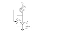
3. Using a potentiometer across the LED, rather than a rheostat in series, creates a more-efficient architecture for constant-current, controllable LED drive.
In the complementary combination of a Dmode FET and a VLED, the FET supplies a current controlled by voltage while the LED generates a voltage dependent on current, and the VLED is driven directly from the drain of Q1. Thus, maximum current flow is supplied to the VLED when the potentiometer is set at the source end of Rcc, with decreasing values selected by Rcc until the minimum current value (determined by the forward voltage of the VLED and the VGS(off) of the FET) is reached at the ground terminal of the potentiometer.
To avoid possibly damaging current flow through the LED, it may be necessary to insert a small resistance between the gate and Rcc, as directly connecting the source and gate together turns the FET fully on. The VF of a single white VLED ranges from 3.6 to 3.8 V, and the VGS(off) of the IXTP3N50D2 FET ranges from −2 to −4 V. This design provides a convenient method of varying the brightness of the VLED over a wide range without regard to the characteristics of a particular FET or VLED, which may be of any color or wavelength. These values also show that the VF of a single white VLED is insufficient to allow the potentiometer to turn the control FET completely off (Fig. 4).
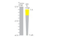
4. Overlap exists between FET control voltage with VLED intensity; yellow shows normal LED operating range.
If a full-on to full-off range is required, the simple solution is to use two LEDs in series. This works over the author’s unit with a 2.8- to 12-V supply range and would work as well up to the voltage limit of the FET; however, it requires a heat sink. A better approach would be to add more LEDs in series to match the supply voltage for heating and efficiency reasons. For example, the 500-V, 3-A rating of the IXTP3N50D2 could control three parallel strings of 100 5-W VLEDs in an offline application.
Rather than the actual value or tolerance of the potentiometer, it’s the ratio of the resistance value above the wiper to that below the wiper, then multiplied by the VF of the VLED, that’s important in setting the voltage on the Dmode gate. The actual value of the potentiometer only determines the current it consumes and is equal to n times the VLED’s forward voltage, then divided by the Rcc value across the VLED (where n is the number of LEDs in series).
For a single VLED with an arbitrary 100-kilohm potentiometer across the VLED, the current is only 0.037 mA (0.14 mW), so any low-wattage trim pot is suitable, which is orders of magnitude better than using a series rheostat. Also, since a Dmode FET is voltage-controlled, the value of the potentiometer could as easily be several times this value and still stay within the transistor’s specifications, further reducing control-circuit power loss to a negligible value. When two (or more) VLEDs are connected in series, the potentiometer value may be increased proportionally to 200 kΩ (or more) to maintain the same level of power consumption.
Further, as the circuit contains no reactive or switching components, it has a unity power factor. Also, it doesn’t create EMI, so Part 15 of FCC regulations concerning emissions don’t apply.
Dan Awtrey (now retired) was in engineering and engineering management, and is a patent holder and author of over 20 articles in print and on the web. He last appeared in Electronic Design (May 1996) with “A Bootstrap Voltage Converter Using A Digital Gate.” Dan may be reached at [email protected].
References
http://www.mouser.com/datasheet/2/228/lz1-00nw05-1174650.pdf

About the Author
Dan Awtrey
Dan Awtrey (now retired) was in engineering and engineering management, and is a patent holder and author of over 20 articles in print and on the web. He last appeared in Electronic Design (May 1996) with “A Bootstrap Voltage Converter Using A Digital Gate.”
Comment About the Article
To join the conversation, and become an exclusive member of Electronic Design, create an account today!

Leaders relevant to this article: