The First Handheld Digital Calculator Celebrates 50 Years, Part 1
Download this article in PDF format.
Handheld electronics have become so ubiquitous to our society that it’s difficult for the younger generations to imagine their lives without them. Whether it’s a smartphone, an iPad, a tablet, an MP3 player, a GPS navigator, or even a digital camera, the common ancestor is the digital calculator.

Thomas M. Okon, COMPLEAT Implementations Team Lead at Concur
It’s been 50 years since the first handheld, digital calculator, known as Cal-Tech, was created by a team of engineers at Texas Instruments (TI) in Dallas, Texas. Their calculator was an extraordinary accomplishment and a big step forward in the field of electronics that inspired even the most experienced engineers. Not only did it serve as the forerunner to handheld calculators, but in the larger sense, it helped kick off an electronic revolution as the first example of a complex consumer device made using integrated circuits.
The story of the Cal-Tech calculator begins in March of 1963, when a 30-year-old named Jerry D. Merryman from Hearne, Texas, showed up at TI to apply for a job as an engineer. He was a self-taught radio specialist working for Texas Research and Electronic Corporation (TRE). He had heard about TI from a co-worker at TRE named Bill Martin, who later became one of the vice presidents of TI.
Willis Adcock, manager of development in TI’s Integrated Circuit (IC) Dept. at the time, was given strict instructions from Mark Shepherd to only hire PhD applicants. Although Jerry had attended Texas A&M University from 1949 to 1952 and 1957 to 1959, he didn’t graduate. Instead what he had was a diverse commercial and academic background, which included several years of designing vacuum-tube and transistor digital circuits.
At TRE, Jerry was involved in the theoretical investigation of a number of liquid-state active devices, most notably the solion tetrode. He also received strong recommendations from Texas A&M professors Walter T. “Walt” Matzen and LED inventor James R. “Bob” Biard.1 They were already working for TI and remembered Jerry’s extraordinary intellect at Texas A&M. As a result, Jerry was hired to work in the IC Dept., which was a part of the Semiconductor-Components (SC) Division.
Jerry quickly acquired skills in semiconductors and was soon making significant contributions to the design of transistors and integrated circuits. His first assignment was to design a sense amplifier for the Monica-C computer system being developed for the Minuteman II missile. Complications arose in obtaining sufficient gain bandwidth in the sense amplifiers, and there was a noise immunity problem in the logic circuits. The performance specifications required 600-MHz transistors, which TI didn’t have yet in integrated circuits.
He wound up designing a high-gain (50 dB), wideband, linear, sense amplifier known as the SN458. It was among the most complex silicon integrated circuits of the day. For the remainder of 1963 and through 1964, Jerry designed integrated circuits that exploited internal optical and thermal effects.
From 1964-65, Jerry worked closely with Bob Biard on the conception and development of an optoelectronic pulse amplifier, the SNX1304 (Fig. 1). Announced in March 1965, this device is thought to be the first commercial optically coupled integrated circuit.
Jerry soon developed a reputation for being a versatile engineer with an intuitive sense about circuit design and an unparalleled ability to respond quickly to difficult problems. According to a former co-worker named Ed Millis, within their group of engineers and scientists, if you had a difficult issue that no one else could solve, the uniform response was, “You need to see Merryman.”
Ed describes TI as being an ideal place for a creative person like Jerry to thrive. According to him, “The engineering and scientific atmosphere at that time resembled slightly controlled mayhem. The groups were running on little management and a lot of enthusiasm. As long as you were working hard on something, the bosses were too busy to interfere with your work.”
22-Bit Bipolar Shift Register
In the spring of 1965, Jerry was working in his office and all of a sudden there was a big shoe on his desk. It was Jack Kilby, the inventor of the integrated circuit, using his desk as a stepping stool. At the time, Kilby was the Deputy Director of the Semiconductor Research and Development Laboratory (SRDL).3 According to Jerry, it was a common occurrence for Kilby to stop by his office to talk about things.
On that particular occasion, Kilby gave him a paper from Bell Labs about shift registers built using four-layer PNPN diodes. Shift registers were commonly used as digital memory. About a week later, Kilby came by again and asked Jerry if he thought the design would save area for memory. Jerry had previously built a shift register that worked at 10 kilocycles using twenty 2D21 vacuum-tube thyratrons. Although they worked, he recalled they were riddled with issues. Jerry told Kilby he thought he could make something better, like a Schmitt trigger. So Kilby told him to go for it. In typical fashion, there was no documentation. Jerry also wasn’t given the reason for the request.
Jerry wound up designing a low-power, bipolar shift register with extreme hysteresis. Bipolar circuitry was chosen for the register, instead of MOS circuitry, because the MOS circuits of the day were unstable. Jerry asked a newly hired employee named Ed Ward to do the layout.
Another group at TI was trying to make a 21-bit MOS shift register. Since they were doing 21 bits, Ed decided to do a 22-bit layout. Supposedly a steak dinner bet was made between Ed and the MOS group regarding who could build their circuit first. In the end, Ed succeeded with the 22-bit bipolar register. A year or two later, it was discovered that sodium ion migration was the cause of the issues with the MOS circuits. Fixing the problem required scrupulously cleaning the diffusion furnaces to remove sodium.
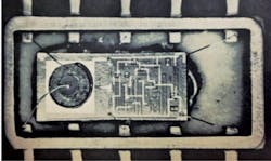
TI’s 1965 annual report describes the 22-bit shift register as a "semiconductor integrated circuit to be used in both industrial and military equipment and systems. It contains 352 interconnected electronic components. TI produces more than 70 of these tiny, highly complex electronic circuits on a single one-inch silicon wafer." The silicon chip, in blue, measures 70 × 180 mils and is contained within the header defined by the gold rectangular border (Fig. 2). The header is made from gold plated metal and either glass or ceramic. The header has leads and a mounting surface for the silicon chip. Wire bonds attach the bond pads on the chip to the leads on the header.
Recruitment Meeting
In late September of 1965, Kilby called a group of senior engineers, which included Jerry Merryman, into his office for a meeting to discuss a new project. The purpose of the project was to build a small personal-computing device to possibly replace the slide rule. Kilby told the group the device would need to have buttons, it should be battery-powered, and there should be a display mechanism for the answers. He pointed to a book on his desk and said it needed to be about that size (small enough to fit in your pocket). However, it was up to them to come up with a plan for how to do it.
According to Kilby, the idea had originally come from Patrick “Pat” Haggerty, TI’s President and Chief Executive Officer. On a business flight to New York, Haggerty told Kilby that he’d like the IC Dept. to take on the task. According to Jerry, Haggerty was a far-seeing individual trying to come up with new electronic devices that could be created using integrated circuits. Many of the ideas he pitched to Kilby would fall by the wayside; however, that wasn’t the case for the calculator.
For the next three days and nights, Jerry worked hard on the logic design. He started out on the first day late in the afternoon by drawing a flip-flop circuit on a board to denote an “Add” button. Then on several sheets of quadrille desk-pad paper, he drew out how to do the arithmetic, how to control the logic, and a rough design of the architecture. What he ended up with was not the complete logic, but it was an excellent starting point. According to Jerry, “It still required a lot more fiddling with.”
After those three days and nights, they all got back together to discuss their ideas. One of the other engineers had come up with a plan to create a device similar to a decade counting unit. The third engineer wanted to make a binary machine that would convert all of the decimal numbers to binary for the computations and then convert them back to decimal.
Kilby wound up choosing Jerry to be the project manager. Jerry always thought he was chosen because his plan was better than that of the others. Apparently Kilby had him in mind for some time leading up to the meeting. Kilby later stated he thought Jerry was probably the only engineer at the time that could have pulled it off, while also handling the management of the project.
After the meeting, Jerry went down to Dean Toomb’s area to report for work, or as Kilby phrased it, “rations and quarters.” A semiconductor components expert named James “Jim” Van Tassel was already a member of Toomb’s group. A few weeks later, Kilby requested a recently hired engineer named Gaynel Lockhart to inquire about joining Jerry’s team. Kilby reasoned that Gaynel was a good fit because of his experience with small-scale, 16-gate arrays. At the time, the group referred to the device as a “slide-rule computer.” They also code-named the project “Cal-Tech.” It was common practice at TI to name projects after universities. In hindsight, Kilby stated he thought the name was poorly chosen to ensure secrecy.4
24-bit Bipolar Shift Register
By December of 1965, Jerry had successfully tested the 22-bit shift register.3 He assigned to Ed Ward the job of changing the geometrical arrangement (layout) of the transistors in order to create a new bipolar, 24-bit shift register. By Jan. of 1966, they had completed diffusions on the 24-bit register.
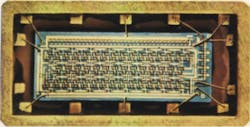
It was the same circuit, practically, except it also had an input and an output buffer transistor. The 24 bits were contained in four sequences of 6 bits on an 85- × 160-mil silicon chip. A 4 × 6 layout was chosen since 24 bits were necessary to represent a six-digit decimal number. Each four binary bits represents one decimal number. Three of the six-digit decimal memories (shift registers) were required to handle all of the numbers entered into the calculator.
As soon as the 24-bit shift register was finished, Ed Ward became disenchanted. The cost of manufacturing everything was a driving factor in the design of the calculator, and Ed was convinced Jerry and Kilby’s plan to make the calculator for $100 was impractical. He wound up quitting the project in order to go back to Purdue to get his PhD.
One of the biggest integrated circuits of the day was a J-K flip-flop with 20 transistors. An individual transistor was small in size and had a yield of roughly 80%. More transistors meant lower yield. With 20 transistors on a single chip, you might get a 3-4% yield.
To build a calculator, they estimated they would need thousands of transistors with at least 83% yield. The probability that it would work was practically zero, so Jerry went to Kilby’s office to express his concerns. He said, "The yield of this thing is going to be 0. I'd like to build it in about 16 chips. Each chip will be more complicated than anything we've ever built. It will be a real challenge."
Kilby didn’t agree. He wanted the team to build everything on one big integrated circuit. He responded with a sentiment he was known for: “You'll just have to think of something.” Jerry didn't know it at the time, but the main goal of the project was to facilitate complicated ICs. TI wanted to branch out beyond military applications and put ICs in everyday consumer products to showcase their widespread capability. The calculator was a means of accomplishing that goal.
Given that predicament, and the fact that TI optimistically scheduled completion of the project for six months, Jerry kind of got cold feet. He soon came up with a plan to make big transistors with simple contacts, merged collectors, no capacitors, wide conductors, and low tolerances.
The Breadboard
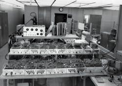
During the development of the calculator, a large breadboard was being constructed to test the calculator’s chips, which they referred to as “bars.” The calculator was also being patterned after the breadboard. The breadboard fit on three conventional sized desks positioned together, each with a top surface measuring roughly 2 × 5 feet.3
According to Gaynel Lockhart, the breadboard consisted of 10 aluminum chassis. Each chassis had 20 cards, which were inserted into connectors on the chassis. Each card had NAND gates similar to the gates in the final calculator. The connector terminals were wired to plug boards on the surface of the chassis. A 3 × 5 matrix display was constructed using number 47, incandescent bulbs to flash the numeric output of the breadboard. The 3 × 5 matrix emulated the dots of the thermal printer that was to be used in the calculator. The keyboard, designed by Jim Van Tassel and his draftsman Weldon Corbin, can be seen in Figure 3 on the bottom right.
One of the engineers working on the breadboard was a mechanical engineer named John McCrady. According to Jerry, one of McCrady’s tasks was to bend tungsten wires and stick them through Plexiglass guides to achieve proper alignment. The tungsten wires would short together with small S-shaped springs. The contacts were 10 mil squares and there were over 200 tungsten 3 mil probes, which had to be perfect.
Sometime during the project, one of the calculator’s four slices (referred to as Array A) had been perfected and word got out to Kilby. He decided to bring the board of directors by to see it. Jerry got it going and McCrady showed up with a handful of little plastic slips 15 minutes before the board of directors. McCrady was upset that his probes didn't always work, so he decided to put the plastic slips between the S-shaped springs to avoid having them short out. By the time the board of directors arrived, the slips had completely deformed the probes, creating shorts between the breadboard terminals. According to Jerry, when they entered a problem on the keyboard, the pilot bulbs on the matrix display “lit up like a Christmas tree.”
The Power Supply
In 1966, the available transistors used too much power for the calculator. For an integrated circuit with thousands of transistors, Jerry imagined they would need something as powerful as a car battery, yet small enough to fit in your pocket. To solve this problem they needed to figure out a way to lower the overall required power. Jerry knew one way to do that was to go way down in voltage. He reasoned they could do everything with a small battery less than 5 V.
They started off with nickel-cadmium cells, but found the cells had high internal resistance, short life, and didn't recharge very well. Jerry saw they were having trouble with that, so he went to the Yardney battery company, where he made the decision to switch over to silver-zinc. Silver-zinc is a lightweight liquid battery that uses potassium hydroxide as the electrolyte. Jerry used three 1.5-V batteries in series to power all of the logic circuitry and the three shift registers.
To lower the overall required power even more, they needed lower current and high resistances. That was accomplished by using collector resistance for the resistors, instead of base resistance. The collector diffusion has a higher sheet resistance than the base diffusion. The resistors are normally connected to the collector. Instead, for the calculator, the resistor would come out of the metal-to-metal contact, which improved the yield a lot. So instead of the gates having an 83% yield, the yield was roughly 93%.
This ends Part 1. Stay tuned for Part 2, which concludes the story behind the invention of the handheld calculator.
Thomas Okon, a Senior Technical Consultant in the field of travel automation software, earned his B.S. in Computer Science from the University of North Texas in 2007. He is the grandson of LED inventor James R. Biard. In 2015, Thomas co-authored a paper with his grandfather about the development of LEDs at Texas Instruments in the 1960s. For the last year he has been mentored in the fields of physics and engineering by Jerry D. Merryman, the inventor of the first digital, handheld calculator.
References:
1. Edwin G. Millis, “Jerry Merryman: the man who killed the slide rule,” (PDF) International Slide Rule Museum, “Making light of the noise problem,” Electronics magazine, Vol. 38, No. 15, pp. 52-56; July 1965.
3. United States International Trade Commission, “In the matter of certain portable electronic calculators,” Investigation No. 337-TA-198, Washington, D.C.; July 1985.
4. Kathy B. Hamrick, “The History of the Hand-Held Electronic Calculator,” American Mathematical Monthly, 102, October 1996, pp. 633–639.

